True true. I haven’t done this because we do mass production. Maybe we could do a speed test app though?
2 Likes
mentioned that only because you talked about raw GPIO usage which pointed to using a bare RP2040 chip for that purpose.
2 Likes
i got a couple from you, one old and now one new, its very nice work. I thank you for the project and your time dedicated to it. sincerely the guy in arizona ![]()
1 Like
That’s great to hear! Thank you for the nice words!
2 Likes
Welcome to the BusPirate forums! ![]()
Your (good) reputation precedes you, and I look forward to your shared thoughts in these forums.
- Henry
P.S. And yes; I have also purchased one of your boards also … recently, so it’s still in transit for now.
2 Likes
I’m are very impressed by your Pico-glitche and library. My friend and I ordered two and spit the cost of shipping. Looking forward to playing with it.
5 Likes
It’s back in stock, so I grabbed one. ![]()
2 Likes
Continuing the saga of my work to do glitching with the BP ![]()
I’ve been doing some hardware hacking on a consumer IoT device for reasons and have been using it as the target for glitching experiments with the BP, mostly without success. I’ve been asking myself why that is, and I’ve made some realizations:
- The device is an ARM A8 running at 900MHz - that’s pretty fast compared to the BP5 at 125MHz. I should really be using my Chip Whisperer against a target like that
- It’s a mature consumer device - the PCB is packed tight with components; a lot of 0402 size SMD, etc. My old eyes and slightly shaky hands are making modifications to the device difficult.
I need to get a little more realistic! So I’ve switched gears and decided to use an Arduino Uno for the target. I’ve got a few of them lying around in a drawer that I can modify as needed and can whip up quick sample code.
Here’s where I am with this:
Glitcher hardware
I used the blank plank for this:
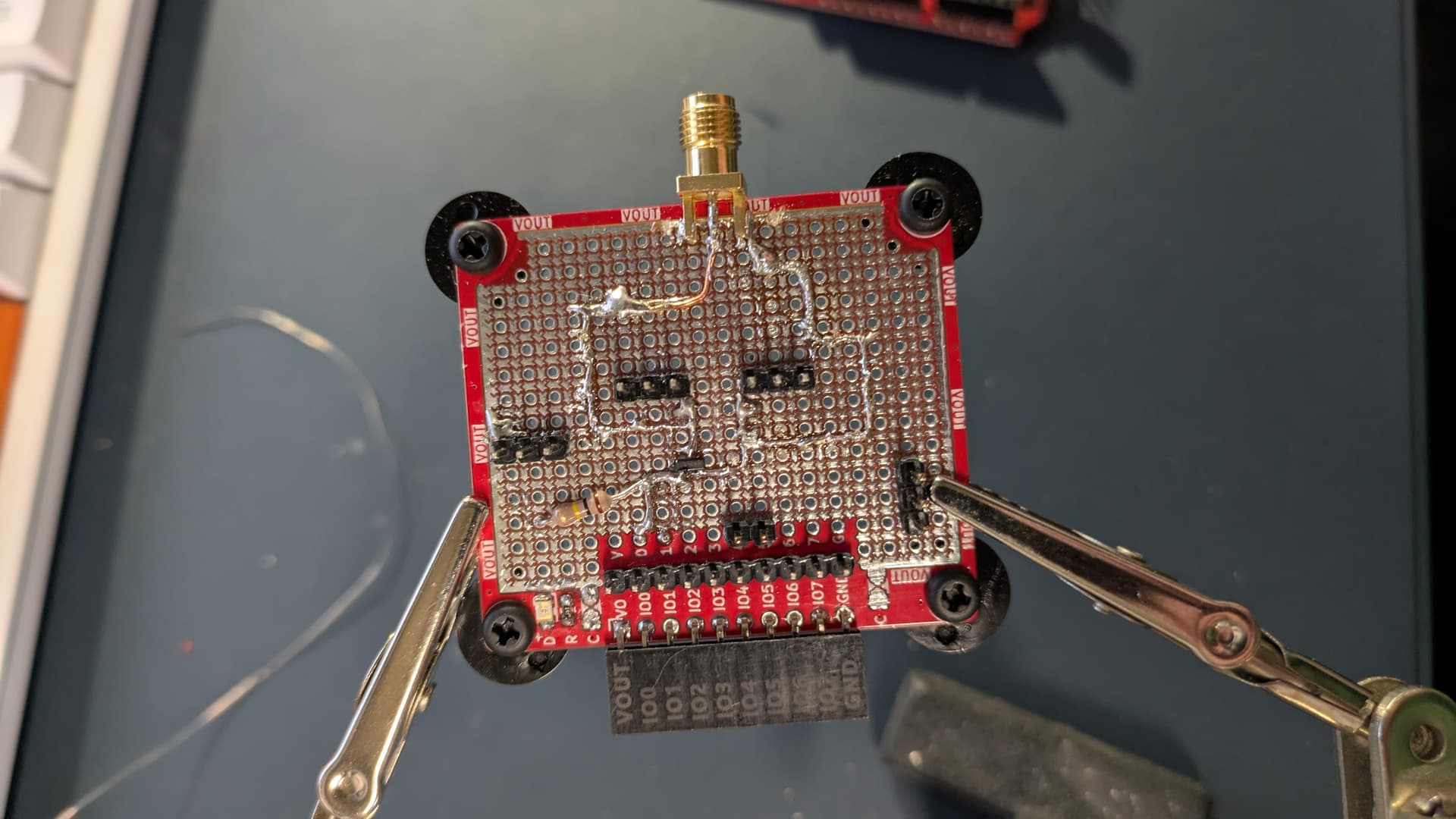
It’s been reworked a few times, but here are the highlights:
- There’s an IRLML2502 N-Channel FET with the gate connected to
IO00. There’s also a pull-down resistor on the gate just in case so it doesn’t drift “on”. - The source/drain of the FET are going to that SMA connector. There are also some pin headers on both sides to make it easier to hook up a scope and other things (I did have to cut the
VOUTtrace on the edge of the plank on each side of the SMA connector; I needed the extra copper on the edge to secure it in place) - There are some ground headers for hooking up measuring stuff
- There are additional header pins for UART TX/RX for connecting a logic analyzer (or other things) for timing measurements
What I did to the Arduino
The board I’m using is the most basic ATMega328P chip at 16MHz; it’s the “Red Board” from Sparkfun. Interestingly enough, there are no bypass caps on the VCC input. I soldered a couple of wires on pin 3 (Gnd) and pin 4 (VCC). These go to another SMA connector that is hot melt glued to the board:
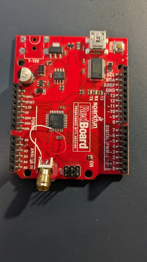
I used SMA connectors on the blank plank and the Arduino so that I could use a short coax cable for the power glitch; I’m trying to prevent any parasitic capacitance or inductance.
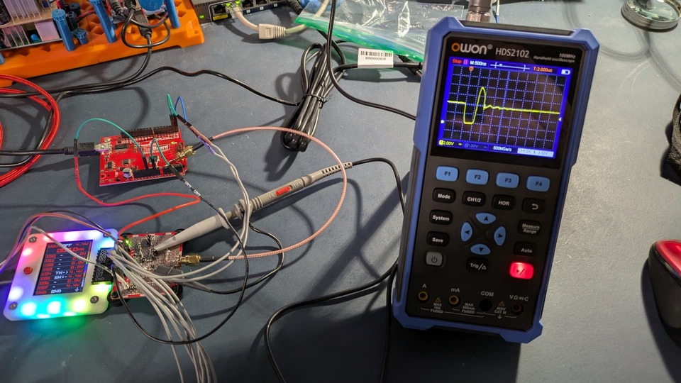
The whole glitching setup
You can see the BP5 with blank plank glitcher hardware. The coax is connecting the plank to the Arduino. A scope is connected to the headers that are across the FET’s source and drain. Out of frame to the left is a Salaea logic analyzer that I was using to set the timing. The pulse is seen on the scope: nice and ugly ![]()
Firmware on the Arduino
It’s a simple UART thing to ask user for a password. Some disclaimers about this code:
- This is almost identical to the actual password code in the “real” consumer device I’ve been working with. Yikes - I know, right?
- The only real difference is that I’m using the Arduino
Serialclass; the real device is usinggetc(),puts(), etc.
- The only real difference is that I’m using the Arduino
- Yes, i know there’s a stack based buffer overflow here. There is in the real device, too.
- Yes, they should really be doing things like:
- hashing user-entered value and comparing to the hash of the password, not just
strcmp()-ing them. Or, at least use something constant time, but hash is best. - add some random short delays between user entry and checking to make finding a glitch target time more difficult
- do not allow user infinite password attempts
- add a back-off delay between attempts to slow attacker down
- … more and more and MOAR!
- hashing user-entered value and comparing to the hash of the password, not just
Anyway, here’s the routine:
int simpleCLILoop(const char* prompt) {

  char password[MAX_PWD_LEN] = {'\0'};
  uint8_t pwdInx;
  int readChar;

  // if password has been entered (consoleEnabled == true), then
  // skip this whole block.  Otherwise keep trying until correct
  // password has been entered.
  while (!consoleEnabled) {
    Serial.println("### Please enter password ###\r\n");  // prompt user
    pwdInx = 0;  // entered password character counter

    // loop runs continuously until <RETURN> key pressed
    while (true) {
      if (Serial.available() > 0) {     // wait for UART rx
        readChar = Serial.read();       // get that char
        readChar &= 0xff;               // mask off lower 8 bits

        if (readChar == '\r') {         // user hit <RETURN>
          break;                        // so break out of forever while() loop
        } else if (readChar == '\b') {  // user hit <BACKSPACE>
          if (pwdInx > 0) {             // if at least one char has been entered
            --pwdInx;                   // decrement entered password char count
            Serial.print("\b \b");      // send backspace, space, backspace over UART
          }                             // to clear the last '*'
        } else {                        // not <RETURN> or <BACKSPACE>
          password[pwdInx] = readChar;  // append the this char to the user's password entry
          ++pwdInx;                     // increment the entered password char count
          Serial.print('*');            // print out an asterix
        } // testing entered UART char
      } // waiting for UART char
    } // main while() loop

    password[pwdInx] = '\0';            // null terminate user entered password

    // compare user entry to "good" password
    if (strcmp(PASSWORD, password) == 0) {
      consoleEnabled = true;            // set bit to indicate password is good!
    }

    Serial.println("");                 // print out a newline
  } // while (!consoleEnabled)

  *consoleBuffer = '\0';
  return (readCommandFromUART(prompt));
}
Results so far?
I spent most of my time today finding parts, constructing and soldering, testing, and coding the Arduino. I wanted to get done before American football playoff games began today, haha.
Anyway, I did get to try it a few times (as the images in the details sections show). Timing was like this:
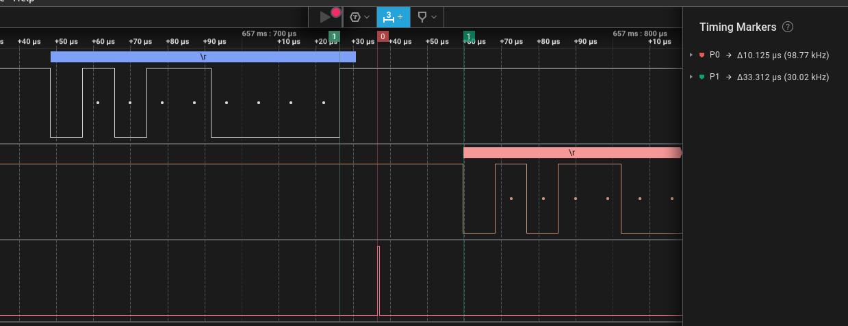
From the end of sending a
\r (return) from the BP as seen on the top line, there is a time of about 33us before the Arduino starts returning the ### Please enter password ### response.
I started with the glitch pulse firing for 450ns at 10us after the BP transmission. Here’s what I saw in the serial console to the BP:
So, I did get a glitch on the first attempts! It wasn’t the glitch I was looking for. I went back into
bridge command, and the Arduino was just spewing junk out the UART.
So yes, a result! (YAY!!). Lots more rewarding progress, and the fun is back in it. I’ll keep working tomorrow and share results.
Also, I plan on putting together a more detailed writeup to share.
6 Likes
Yay, I have reliable glitching with the BP5 and an Arduino! ![]()
Here’s the BP serial console (with notes):
Getting BP connected and set for UART mode:
VT100 compatible color mode? (Y/n)> yScreen Resolution changed
HiZ> m 3


Use previous settings?
 UART speed: 115200 baud
 Data bits: 8
 Parity: None
 Stop bits: 1
 Hardware flow control: None
 Signal inversion: Non-inverted (Standard)

y/n, x to exit (Y) >

Actual speed: 115207 baud
Mode: UART
Running bridge command while resetting Arduino. Arduino displays a simple power up header, then starts asking for password:
UART> bridge
UART bridge. Press Bus Pirate button to exit.
Test glitch target (victim), v 0.9
### Please enter password ###
Hit the button then run the glitch command:
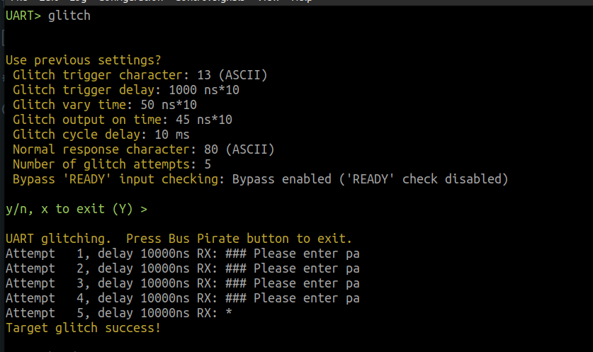
UART> glitch


Use previous settings?
 Glitch trigger character: 13 (ASCII)
 Glitch trigger delay: 1400 ns*10
 Glitch vary time: 5 ns*10
 Glitch output on time: 10 ns*10
 Glitch cycle delay: 100 ms
 Normal response character: 80 (ASCII)
 Number of glitch attempts: 5
 Bypass 'READY' input checking: Bypass enabled ('READY' check disabled)

y/n, x to exit (Y) >

UART glitching.  Press Bus Pirate button to exit.
Attempt   1, delay 14000ns RX: $>
Target glitch success!
It glitched past the password on the first attempt!! (I can usually get it within 3 or 4 attempts). go back to bridge command:
UART> bridge
UART bridge. Press Bus Pirate button to exit.

	<executing  ...>
$> ls
	<executing ls ...>
$>
So, what’s happening here is that I didn’t write a command line interpreter, lol; instead, it just echoes back whatever you enter and gives another $> prompt. See previous post for info on Arduino firmware, etc.
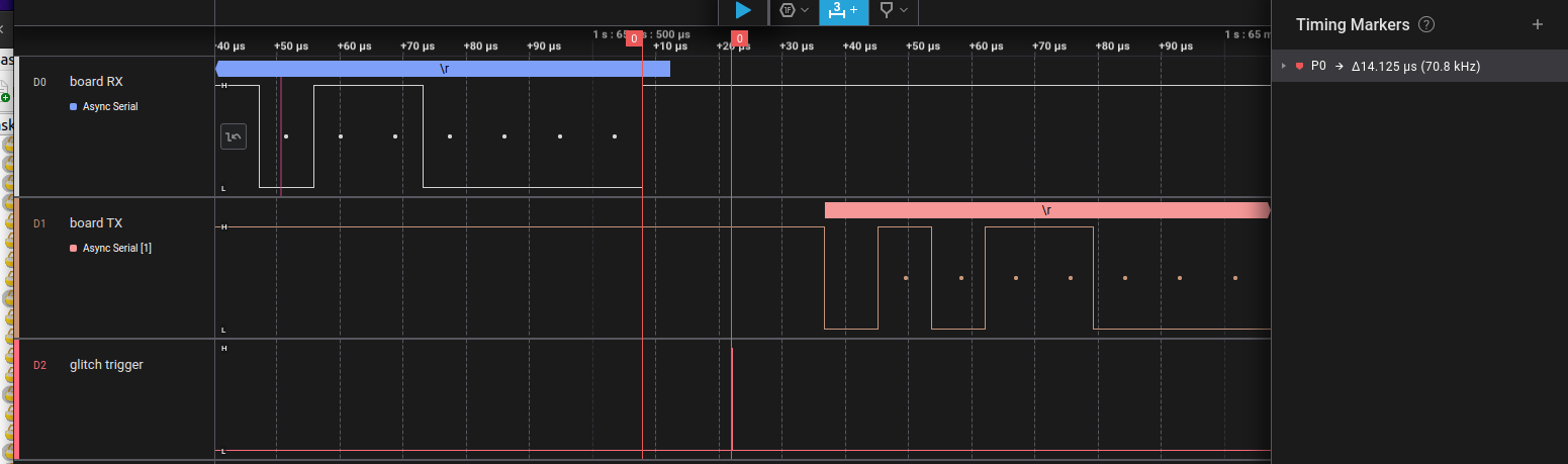
In the logic analyzer (an external one, not the built-in) channel 0 is TX from the BP, channel 1 is RX from the Arduino, and channel 2 is connected to IO00, the gate of the glitch transistor:
The setup on my desk:
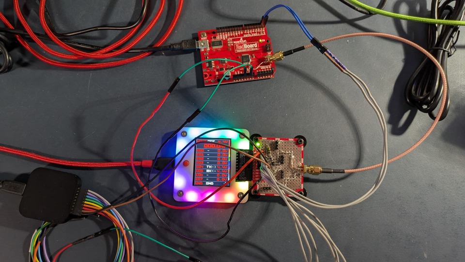
Note - good thing I ordered 40 FETs; I had to replace it already. I had the glitch time too long at first and burned it up. Ooops.
6 Likes
I am truly impressed!
3 Likes
Wow, really impressive!
I’ll get an Arduino and try it myself!
This sent me down a bit of a rabbit hole. It may not be useful for your current situation, but may help someone in the future:
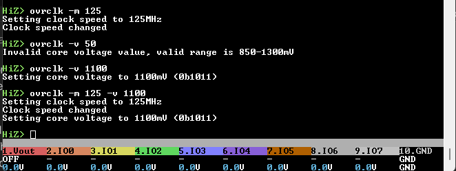
There is a new command ovrclk that sets the core speed and voltage. It seems like 270MHz is pretty doable, and the core voltage doesn’t really help until you get beyond that. However, note that the limiting factor becomes the Winbond SPI flash chip the firmware is stored on.
The command is in simulation mode in normal firmware builds and displays a warning that it doesn’t actually do anything.
/*****************************************/
// OVERCLOCKING CAN DESTROY YOUR HARDWARE
// USE AT YOUR OWN RISK
// NO WARRANTY IS PROVIDED
// NO LIABILITY IS ACCEPTED
// NO SUPPORT IS PROVIDED
// The command does nothing unless
// compiled with BP_OVERCLOCK_ENABLED
//
// #define BP_OVERCLOCK_ENABLED
/*****************************************/
To enable the command uncomment #define BP_OVERCLOCK_ENABLED and compile the firmware.
I would consider adding this command to the main firmware (with more warnings, and multiple confirmation steps) when the OTP is going. Then we can burn a “warranty voider” fuse when it is used ![]()
3 Likes
Oooh, I’ll have to check out the overclock ![]()
2 Likes
Let me know how it goes for you!
I was shorting pins 3 and 4 on the 328P.
By the end of the week I’ll have a full, detailed writeup that I’ll share a link to.
3 Likes
should only burn the fuse if you overclock and not if you downclock (which might make sense, too to use when you need to get a prescaler to fit)
3 Likes
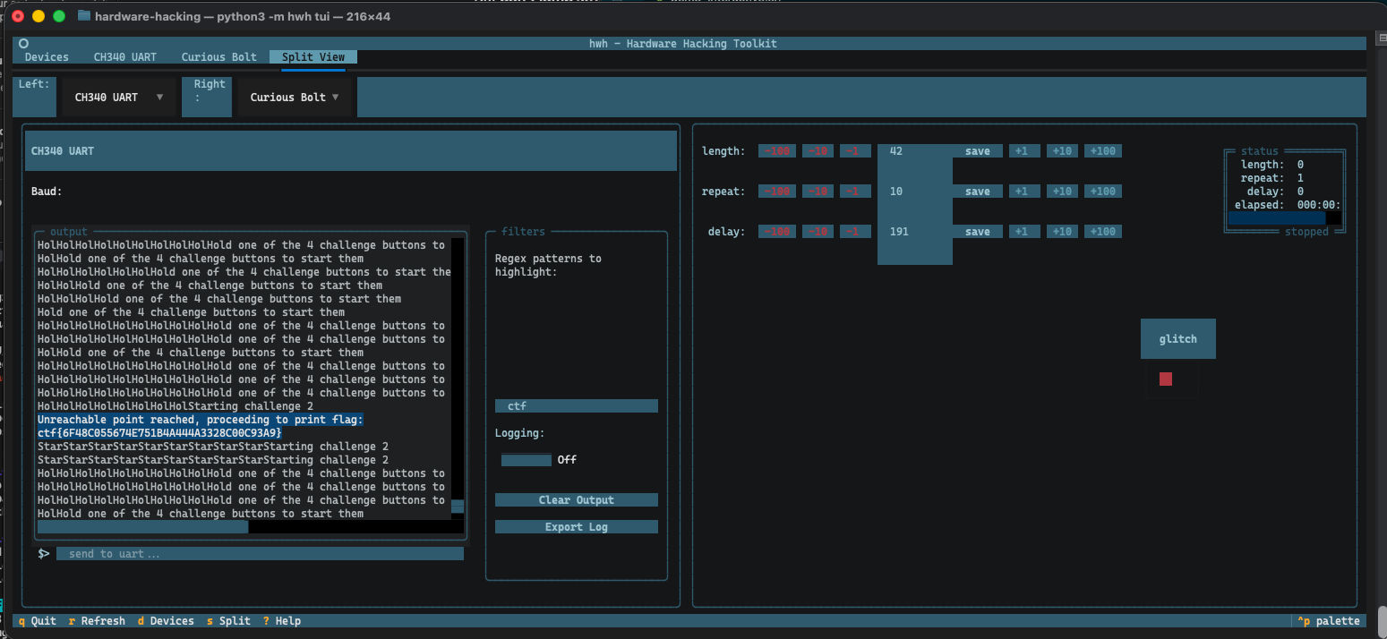
Quick plug for something I’ve been working on. I personally went with a curious supplies bolt for glitching and created a TUI to show side by side UART output and glitch controls. It’s pretty basic for now, but I’m hoping to enhance with more features for BP. I’m hoping to get UART passthrough and glitching implemented with flatbuffers to have BP be the primary driver. The Bolt CTF device that comes with it has been great for learning, we need more devices like that.
3 Likes
Very nice! Thank you for sharing.
1 Like
This looks very interesting indeed. I will have to look at this.
I’m still waiting for my Sword of Secrets
.
Me too! I did everything I could with the online version (which I did fully solve … both original and gold). It is an extremely well put together CTF, with stages teaching something, and using / expanding that learning at the next stage. Total bummer about the shipping SNAFU, but … I’d have been more surprised if it hadn’t happened, given the environment.
1 Like