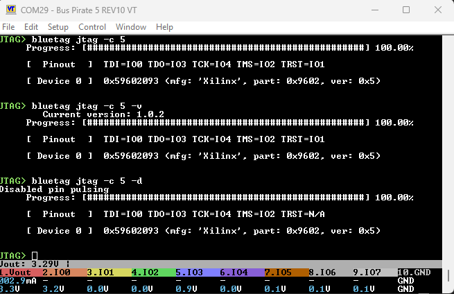
I notice I occasionally get the wrong ID and device, but the correct pin out. I imagine there is still a bug in here, or maybe it’s my setup. After I check all connections it works consistently for a while.
This port is way cooler than I expected! Keeping the original interface was a nice touch. I’m definitely feeling mixed emotions right now . I’ve been working on a major update to my project and ended up adding a lot to the base. Ian’s changes just reminded me of how much cleanup I still need to do at my end.
Not yet, unfortunately. I still struggle with version control systems, so I work locally and push updates to GitHub. I know it’s not ideal, but I’ll get there eventually. I can share a screenshot of the new interface via DM, as I understand it’s not appropriate to post it here on the Bus Pirate forum.
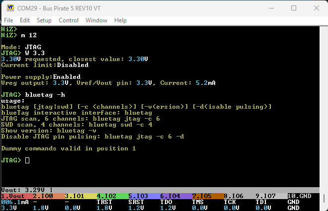
I’ve been wanting to add functionality to use blueTag as a JTAG/SWD debugger, similar to JTAGulator, if it can correctly identify the target pinout. Since blueTag is meant for RP2040 dev-boards, providing an alternative when the proper hardware isn’t available, my goal was to implement this efficiently. It turns out, Bus Pirate’s OpenOCD interface worked perfectly, so I didn’t have to reinvent the wheel. OpenOCD already supported Bus Pirate, it uses a serial interface, and the protocol was well documented.
Once that was in place, I got a bit carried away and added support for blueTag to function as a USB-to-Serial adapter. I also implemented support for Flashrom’s “Serprog” protocol, so it can now read and program supported flash chips. I even ported RPi’s DebugProbe function because I found my Bus Pirate SWD implementation to be relatively slow.
Right now, I’m struggling with protecting the GPIOs and figuring out how to reliably detect if a channel/GPIO is connected to GND or VCC/Power. While detecting GND or VCC is fairly straightforward, distinguishing between logic HIGH & VCC/Power or logic LOW & GND without external components is proving to be a challenge.
Wow, so that’s the old school Bus Pirate v3.x mode? With the new hardware we currently use two alternative firmwares (pico probe, dirtyJtag) to provide JTAG.
Nice work!
I was going to suggest this. pico probe uses the PIO and I think most stuff is a bit speedier with the PIO. It also has a mode that accommodates a bidirectional buffer, like those on the Bus Pirate 5.
I had planned to implement something similar. The Bus Pirate has serial resistors on the buffered IOs, so there is a current max limit. I assumed it would be better to quickly short to ground/power and then check if the values matched, than doing several scan cycles directly into power or ground.
The power/ground check would run first, generate some warnings/recommendations, and then the user can decide to skip those channels in the scan (or not).
Something that isn’t perfect seems better than shorting IOs directly during scanning For example my test target has 5 grounds and 1 3.3volt pins on the JTAG header. I excluded them by inspecting the PCB and measuring with a multimeter, but I think it would be possible to be pretty accurate and automate it.
Let me know if I can help in any way. I had fun porting the project and it is one of the most requested features.
I’d say this is a prime example why I suggested the new pullups and pulldowns with several resistor values for the new BusPirate Rev. 7. Measuring port impedance with this new setup would be so much better for this use case.
This is exactly what I was thinking as well But it would not be backwards compatible, so a nice enhancement for 7 with a simpler fallback method perhaps.
Yes, sticking with the old method for now. Tweaking the USB stack always makes me a bit anxious. The initial plan was just to add JTAG/SWD support as a quick update and move on. But in the end, I ended up using the TinyUSB library to implement DebugProbe.
I plan to do the same—detect unsafe connections, warn the user, and let them decide whether to include or exclude them.
That seems like the best approach. Setting the GPIOs only as input with RP2040’s internal pull-up/down resistors still gives false positives. The only option is to briefly toggle them as output and run extra checks for accuracy.
Absolutely!
I aimed to keep it close to the official CMSIS_V5 implementation (surprisingly easy!), so mine identifies as a CMSIS-DAP programmer but doesn’t use PIO. It’s more closer to DapperMime than DebugProbe in that regard. The official CMSIS_V5 implementation supports JTAG, but none of the current programmers seem to enable it. I should be able to activate that in the future if there’s interest. Plenty of room for improvement!
Thanks for the support! I’ll tidy up my project, push it to a dev branch, and let you know. Also, working on the Buspirate port of the OpenOCD protocol was fun—I appreciate its simplicity. There was an ASM function that briefly had me puzzled, but by the time I saw it, I was already too deep in to turn back. Had to just roll with it!
Could this be done with a PIO program, at least on RP2350?
MOV PINDIRS, NULL and MOV PINDIRS, ~NULL changes the direction of all OUT-mapped pins in a single instruction … so you can swap pin direction in a cycle-accurate way. Would still need to let pin state settle for at least two cycles, but … very short times indeed seem possible?
Would this ensure you can toggle the direction fast enough to not burn things out? Reading the pins would also be trivial, so you could just dump a bunch of the pin states (high vs. low) into the UART FIFO for the main firmware to pickup after it executes?
That’s pretty clever, I like that. This would work great on BP6+ or bare pico, but we’ll have to use the analog mux on the BP5 because it’s the only way to see beyond the buffer.
I like the idea of loading up a FIFO with 8*16 bit words that control pin state and buffer direction. A simple 2 or 3 cycle delay between PULL and then an IN to sample the pins.
I thought the FIFO could be the way to extract the pin states, but I suppose it could also be how to control the pin states also. Reduces the complexity of re-encoding the PIO program dynamically. Nice.
I’ve spent the past few days on this but haven’t found a practical (programmatic) solution yet.
In theory, with blueTag using only internal pull-up/down resistors, I can reliably identify these GPIO states when connected to a target:
Logic High
Logic Low
Floating
While toggling GPIO to output mode can help verify these states, it isn’t necessary. The main issue is that there’s no clear way to differentiate Logic Low from GND or Logic High from Power/VCC.
To make things more complex, on the STM32 I’m using for SWD testing, the SWDIO pin is held High. Ignoring it means the scan will always fail. Similarly, if a target pin defaults to Low, there’s no way to distinguish it from actual GND.
For now, the only mitigation is to keep blueTag GPIOs in output mode only when absolutely necessary during the scan. While not a perfect solution, it minimizes the risk of damaging the dev board (blueTag) and the target. Currently reviewing the scan logic again. Open to suggestions!
It’s a tough one. The target I test with is a CPLD board and it has pull-ups on all the data pins. They are 10K, so much more powerful than the internal pull-up and pull-down in the RP chips (65k?). It wouldn’t be possible to detect them in this way.
I think one possible solution is a very small (100s of Ohms) series resistor to protect the pins, and then just straight up short to power and ground. However, then the pin can’t observe the other side of the series resistor so you need a second set of pins to see if it is actually high or low.
The Bus Pirate has this hardware in various ways. They all have a small series resistors in the IO to protect pins. BP5 has an analog mux that can measure the voltage on the “real world” side of the series resistor. BP6 also has a second buffered input to see the “real world” side of the series resistor.
Just pushed initial v2.0.0 release to GitHub to the master branch. Documentation is still a work in progress but the build is fully functional. This update includes some improvements and bug fixes for JTAGulator-specific functions too. Everything works as expected on my test devices. If no major issues surface in the coming weeks, I’ll submit an update to the Bus Pirate repo.
I read through the update this weekend and it looks great! You packed a lot of stuff in there, and I especially like the using pins to determine the default startup function.
In terms of a Bus Pirate port - have you had a chance to see the structs I used in the port of 1.x? I tried to eliminate most global variables and pack them into a struct for slightly easier handling.