At least there’s no hardware crisis ![]() The bug is in the logic analyzer firmware, not the hardware.
The bug is in the logic analyzer firmware, not the hardware.
At least there’s no hardware crisis ![]() The bug is in the logic analyzer firmware, not the hardware.
The bug is in the logic analyzer firmware, not the hardware.
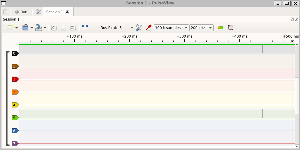
Got pulseview (linux nightly) running in WSL2. All the issues I had with the windows version are gone! I get garbage data the first few runs, going to look into that.
I’m going to push the latest logic analyzer updates now, any tests would be appreciated.
What works:
It’s so nice to have pulseview working right, I made more progress today than I have all week.
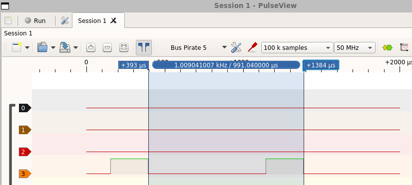
Looks like I’m getting good and repeatable data now under Linux, was able to decode UART and see PWM square wave across multiple captures and sample rates.
I did however have to connect to the BP first and turn on the PSU manually, otherwise I got nothing over the line. It seemed from one of the previous messages that it was going to be enabled by default when the BP is in LA mode, has this not been implemented yet?
Also, as you said, the first capture was garbage and I had to change sample size before things started working.
Excellent thank you so much for testing. I’m glad it’s improving.
The latest auto build has a test logic analyzer UI.’
logic -h will print help
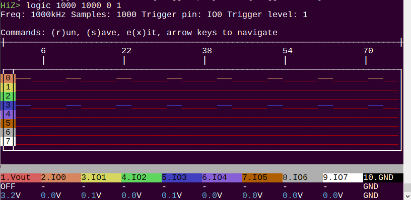
logic {frequency in kHz} {samples} {trigger pin} {trigger level} - logic analyzer. {frequency} 1kHz-62500kHz, {samples} 100-128K {trigger pin} 0:7, {trigger level} 0:1.
Example use: (1000kHz, 1000 samples, pin IO0 trigger, high trigger):
HiZ> logic 1000 1000 0 1
Commands
r to run a new capturex to exits to save to binary blob (la.bin)Adding the logic analyzer was really slow going because it was a giant fight with sig-rok. I really like sig-rok, and it’s grown to look really cool over the years. However, it is almost always the case that the various support modes don’t all get updated to the latest and greatest. It’s really really common to find custom compiles and “temp, use this version patch pending” kind of stuff.
While the Bus Pirate will never beat a good piece of LA software, I wanted to add some kind of quick and easy interface so I can finish up the LA without debugging sig-rok at the same time.
Bugs:
Todo:
I think the UI is pretty usable if anyone is interested in testing.
I will finish up the to-do list and then it will be a breeze to close out pulseview/sig-rok integration.
Up next: SPI binary mode for flashrom, and while we’re doing flash chips, I’d like to cleanup and finalize the build-in flash program and dump commands.
This is very cool! As I understand it, the BP can only do one thing at a time, so if I wanted to use the logic command to debug something like the I2C bus error, I would need two BP’s, right? I happen to have two as I have the Rev8 and Rev10. So I can do that.
Very very minor bugs which I hesitate to mention because you are working so hard… - The “logic” command isn’t on the help page.
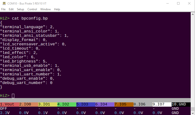
Also - I tried “cat bpconfig.bp” and there was a NL at the end of each line, but no CR, so it was a messy display. No big deal.
Or perhaps “logic” could be an option in the “d” (display) mode.
The problem with watching what the bus pirate outputs is that we’re behind the buffer, and frequently (I2C, 1-Wire) we’re manipulating direction instead of IO, and it’s inverted to get the right signaling for open drain busses. So the RP2040 doesn’t always have a clear view of what’s actually going on after the buffer.
One thing that I’ve considered is using eg half the pins as a 4 bit logic analyzer connected to the in-use IOs. This should be do-able. I have a much better solution, and even have a board for it, but won’t have time to fiddle with until at least the fall.
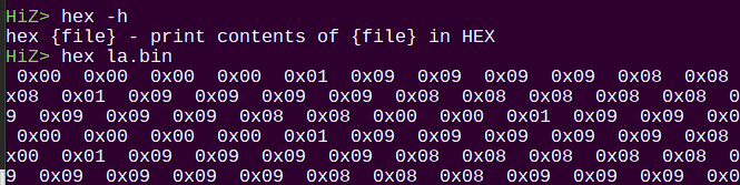
Great call on cat! it annoys me too, and I literally have that open, copying it to a crude way to show the HEX values of the logic analyzer dumps so I can verify it’s working. A firmware will pop up shortly with this command. I’ll look at cat
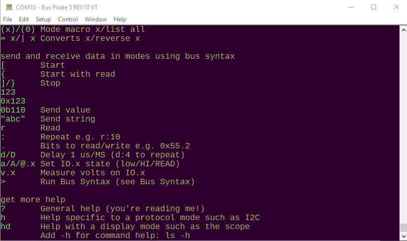
The help menu is unmaintainable, and takes ages to update. It’ll be faster to rework it than add new commands. Sorry about that, it annoys me too and it is at the top of my list.
Reworking the help would be better in the long run, especially if you assume a VT100 screen. It could be scrolled, expanded, have examples, and have -h built-in (without executing “cmd -h”).
But that’s an extra feature. I do like the 4-pin logic analyzer idea for some of the modes like I2C. It’s awesome to see this thing evolve.
I pushed updates for the logic analyzer. I believe it’s in pretty good shape now.
I’d like cycle through traffic light colors during captures. Armed (red) capturing (yellow) and dumping (green) then back to whatever was playing. The way I tried to detect the trigger was not well thought out, so it’s yellow->green for now.
I had a look at this best practices guide, then studied git’s help. I came up with a struct and parser to use everywhere in a standardized way, and hopefully do all the tracking for consistent tabs widths.
I’m aiming for three sections, though all three won’t be used everywhere.
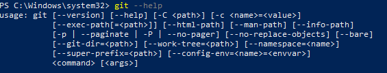
First is usage examples. This will be specific to command -h help I assume.
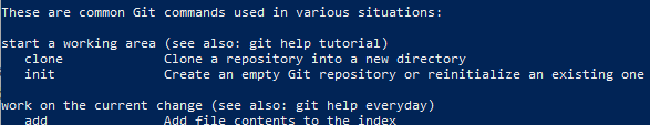
Then a list of “common” commands. git does subcommand info, but that kind of feels like our -h. Not sure how we’d handle that, but I’m open to it.
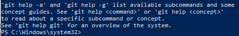
Finally a bit of info about getting more help.
I pushed these changes if anyone would like to test them.
Love the onboard interface, but still a bit confused why the default isn’t to turn the onboard PSU on as soon as the BP switches into LA mode if it won’t work otherwise. At the very least, there should be an onscreen warning/reminder that LA mode needs power to be turned on manually.
For much the same reason, it seems like the logic analyzer should be its own mode and not something that can be used from HiZ mode. My understanding was HiZ mode is intended as a “safe mode” where you can’t turn on power or send data, so being able to use the LA (or scope) in HiZ seems very counterintuitive.
Thank you so much for checking it out and the feedback. Good points.
The onboard (in firmware? in terminal?) UI was just an itch I wanted to scratch on sunday evening that helped me get the sig-rok support debugged. You’re right, it’s counter intuitive as it currently sits in HiZ mode with no power available.
The sig-rok/pulseview access mode does enable a 3.3volt supply now. This is probably fine for 95% of cases. Here’s some things I haven’t quite figured out yet:
c config menu option (given how laggy adding that to sig-rok client might be)?
Today I’ll try to get it to the point where having a logic command in any mode is something that makes sense, and is maybe even a bit delightful ![]()
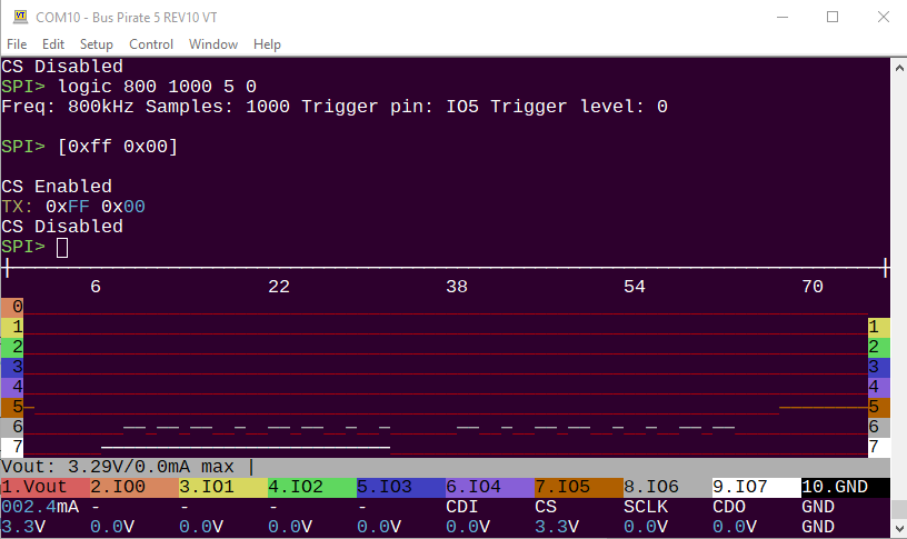
This is were I’m trying to go with the UI LA. The LA is now part of the menu bar and follows you around in various modes. It updates every time it sees the trigger, or every 30 seconds in auto mode. Here it’s triggered on CS falling in SPI mode.
This is too dirty to push to main, but I’ll push to a branch. Issues:
It’s a bit silly, yes. It is defo no substitute for pulseview. It could be someone’s first dead-easy introduction to a logic analyzer with minimum levels of fuss. I’ve enjoyed using it for sanity checks while I’m developing the Bus Pirate itself.
Part of getting this going is straightening out the sdk I2C PIO, which is a priority. I also notice I2C isn’t loading previous baud rate for reasons I don’t yet understand - anyone else see this?
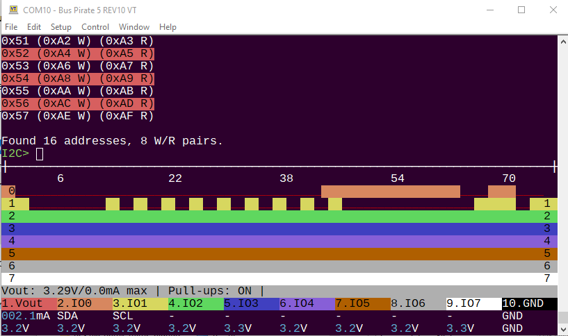
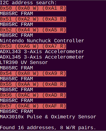
Production is incoming, so I need to add some new stuff to the self test. I’ll also try to pull together something that lists possible I2C devices by address.
So, it turns out I’ve been pushing to the wrong branch all day, so a bunch of updates are about to arrive:
The terminal logic analyzer improved a bit.
logic 400 1000 0 0 for 400kHz, 1000 samples, trigger pin 0, trigger state 0 for example. Update settings by running the command with a new configuration.logic without any arguments enters a control mode: left/right arrows to navigate, r to rearm/recapture, s to save to binary, x to exit the logic analyzer. This is the bit that still needs work.From this thread, there’s an update to I2C address search macro (1). There’s a new search macro (5) that lists possible devices using the Adafruit I2C address list.
There is also a new step in the self test we used for final volume production testing today. It checks specifically for the op-amp not connected bug in REV10 batch 1.
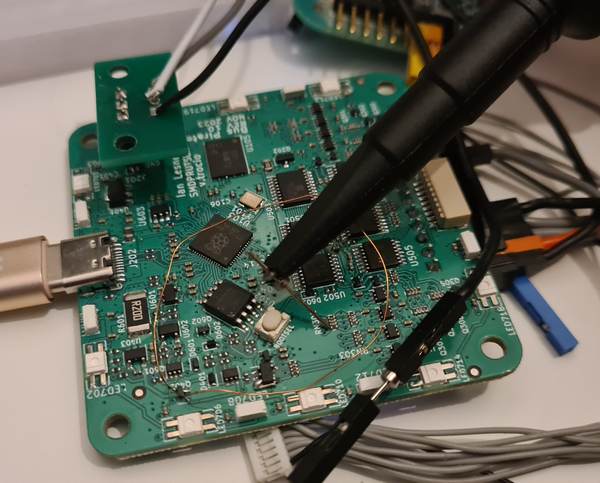
By request, I’m getting some smart IC cards (SLE4442, etc) to work on in 2wire mode. The idea is to move this kind of script into the terminal. A cheap card socket seems to be YeXin KF-011C (PCB above).
format (storage) command to help. pause command which will be used for the tutorial/script mode I’m cooking up.Sorry everyone, not much firmware activity today. Hardware production is now fully sorted.
We opened our office two days before the holiday ended so we could be fully ready Monday, but the factories are still short staffed and dragging a bit. The PCBA boss was supposed to meet with us Monday, but instead we talked to him Tuesday/Wednesday while he was stuck in one of those 100km long traffic jams on the way back to Shenzhen.
We were short 1500 diodes to make a larger batch. The rep went into the (empty) factory and found a partial reel still on a reeling machine to send us. Everyone has been super helpful.
We’re still pretty much on schedule, and from here the process should just play out.
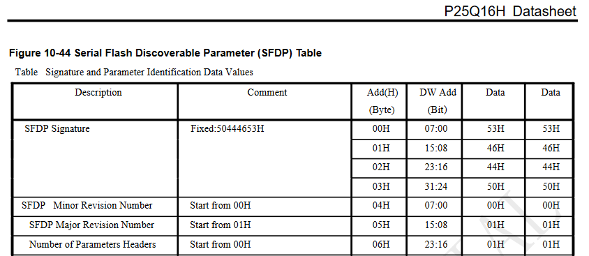
I soldered 3 different flash chips with SFDP info. Now I’m going to grab and parse that from SPI binary mode, and a script built into the Bus Pirate. Then I’ll get some implementation of flashrom working.
We also need an updated binary bitbang GPIO mode that takes advantage of all 8 pins.
The latest firmware has a new macro (1) in spi mode that reads and reports on flash SFDP tables. More on that here. Next, I’ll add a universal flash program/read script I came across.