There hasn’t been a chance to do a proper change log, but here’s an overview of the hardware updates to Bus Pirate 6:
1.1volt LDO
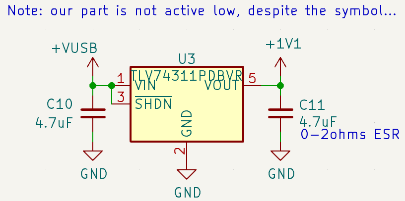
As the comment makes clear, this was a rush job ![]() The Texas Instrument 1.1volt regulator supplies the Rp2350 core. It’s about 0.3RMB, while using the SMPS is ~1RMB. The LDO takes less room and is less fiddly.
The Texas Instrument 1.1volt regulator supplies the Rp2350 core. It’s about 0.3RMB, while using the SMPS is ~1RMB. The LDO takes less room and is less fiddly.
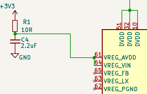
Still need to power VREG_AVDD and VREG_VIN. It works without VIN powered because an early datasheet didn’t mention it so I didn’t connect on the first board version. When reviewing the board Rpi said to connect it.
74HC595-ectomy
The IO expanders are gone. Opens up board space, relieves pressure on the internal SPI bus shared with the LCD and NAND flash, etc. Great update.
We still need a level translator for the various 5volt signals on the board (amux select, pull-up enable, LED data). The 74HCT245 is changed to DFN package, which is about 10x more expensive than the TSSOP version. Only Nexperia and TI parts are available, no Chinese domestic manufacturers currently make this chip in DFN. WuXi I-Core may start selling one soon.
74LVC8T245
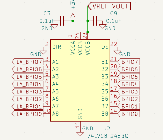
This 8bit buffer runs at 3.3volts on the Bus Pirate side, and from VOUT_VREF on the other. It is fully qualified for partial power down operation. It’s pretty fast too.
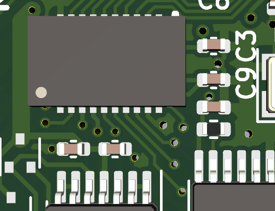
Another DFN part. These are super expensive in cut tape. Initially it was a Nexperia part, but Wuxi I-Core just started making their equivalent in DFN and it’s about half the price. TSSOP version is probably ~0.65RMB, but the DFN is 4-8RMB.
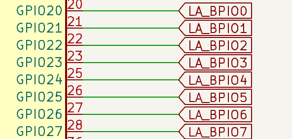
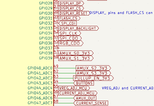
The buffer connects to the outermost point of the buffered IO pins, and to GPIO20-27 on the RP2350B.
Over current detect
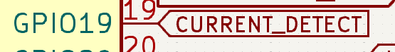
This was read through the analog mux with the ADC due to lack of pins. Now it has a dedicated pin, but currently the firmware still reads through the mux.
Series Resistor
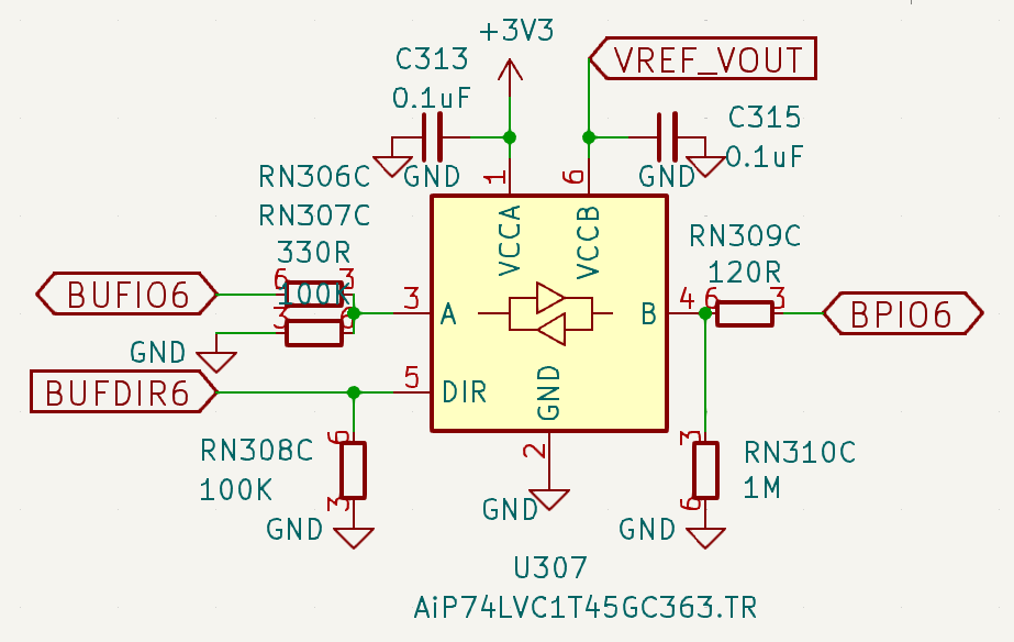
Forgot this one: Decreased series IO resistor from 330ohms to 120ohms. If that doesn’t give us any issues, I’ll decrease it to 70ish ohms in a future revision.
Free pin

Yup. One spare pin.
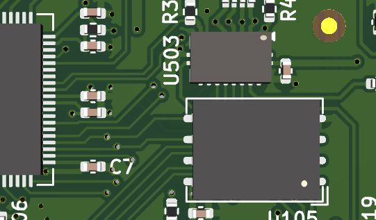
PCB
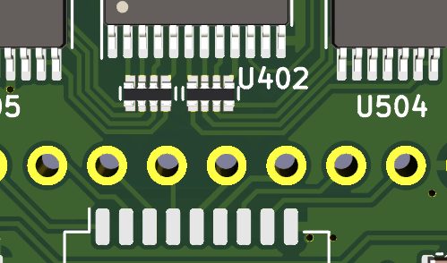
The analog area and the RP2350 area of the board were reworked quite a bit. The internal layers are mostly ground. In the future I’d like to rework the front end. The resistors by the 10P connector are a nightmare in production (hand soldering the header constantly causes shorts that have to be fixed). I’d also like to add additional protection diodes and TVS diodes on each pin. It’s really tight in there so that may be more aspirational.