RP2350: Bus Pirate 5XL and 6

image

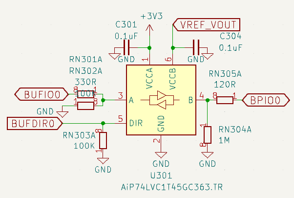
A brief explainer: This is a single bi-directional IO buffer that drives pin (BP)IO0 on the 10p connector.

DIR A B
High Input/High Output/High
High Input/Low Output/Low
Low Output/High Input/High
Low Output/Low Input/Low

BPIO0 to B pin is input and output from the “real world” on the 10p connector. It has a 1M pull down to ensure pins don’t float. It also has a 120R series resistor to protect devices and the buffer.

BUFDIR0 is the RP2350 pin that controls the buffer direction pin (DIR). When high, it outputs A->B, when low it outputs A<-B. It has a 100K pull-down so it starts as a safe input before the RP2350 is fully initialized.

BUFIO0 is the RP2350 pin that controls the buffer HIGH/low output level using the buffer A pin. It has a 330R series resistor to protect the rp2350 and buffer during accidental bus contention.This is key: It also has a 100K (1M in 5) pull-down resistor to hold it weak low when the rp2350 gpio pin is an input.

Open drain bus types (1-Wire, I2C, 2Wire, HDUART, etc) require a pull-up resistor to create the high level. Masters and Subs sharing a bus pull the wire low to ground, and then make the pin high-impedance (like an input on microcontrollers) to release the bus and let the pull-up yank it back high.

So, the meat of the issue: when driving open drain bus types from the PIO, we toggle the DIR pin of the IO buffer to make the B (real world side) output high-impedance (input, DIR low A<-B) or an output ground (output, DIR high A->B). The RP2350 GPIO pin, BUFIO, is always an input held low by the pull-down resistor. This creates a low on the bus without needing to somehow change the RP2350 GPIO (BUFIO) from input to output/ground in the PIO program (which while possible, is an absolute mess and IMHO not a workable solution). We depend on that 100K resistor to keep the bus low when we output.

E9 errata essentially means that once the pins are exposed to a high level, they latch up and stick at a high level (2.1volts). They latch up so hard the 100K resistor can’t pull them down (reportedly <9K works). When the buffer is high-impedance on the bus (input to the RP2350) the pin sees the external high level and latches up. When we change the buffer to output from the RP2350 to the bus, instead of a low/ground it outputs high. Basically, we can’t create a low level on the bus because there’s no way to output low once the pin has latched.
3 Likes

Small updates:

E9 errata in its original form appeared on Hack a Day yesterday.

Raspberry Pi got back to me: they’re looking into it.

Matt Mets at Blinkinlabs convinced me that I won’t be relentlessly trolled for adding a 5K pull-down. I don’t have a 5K array, but I have 2x10K. I’m going to try to stack two of them, but those 4x0402 arrays are crazy small.

The second batch of Bus Pirate 6 was pulled from production when it was literally mounted on the PCBA line. If you have a back ordered Bus Pirate 6, I’m super sorry, but we need to fix this issue before we make another batch. Dirty PCBs has a self refund button, so it’s easy to bail at any time with no hard feelings :slight_smile:

Finally: if there is no software fix from Rpi for this bug, we will send everyone in batch 1 an updated board as soon as it is possible.

7 Likes

ImportedPhoto_1724939744768

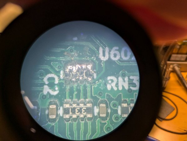
So this is kind of fun. Visited Matt Mets at Blinkinlabs (a US distributor of the Bus Pirate), and he soldered tiny 4.7K 0201 resistors on top of the 100K 4x0402 resistor array. He also convinced me that I probably won’t be trolled mercilessly for using such a low value pull-down, I’m not sure which job was harder.

DIO> bug e9
Replicate bug E9

Test 1:
Pull-down disabled...
Disabling Bus Pirate pull-ups
Making IO0 buffer and GPIO input
Making IO0 buffer an output
GPIO pin should be 0: 0
Making IO0 buffer and GPIO input
Enabling Bus Pirate pull-ups
Making IO0 buffer an output
Disabling Bus Pirate pull-ups
GPIO pin should be 0: 0

Test 2:
Set pulls disabled...
Disabling Bus Pirate pull-ups
Making IO0 buffer and GPIO input
Making IO0 buffer an output
GPIO pin should be 0: 0
Making IO0 buffer and GPIO input
Enabling Bus Pirate pull-ups
Making IO0 buffer an output
Disabling Bus Pirate pull-ups
GPIO pin should be 0: 0

This is a drastic step, but it did indeed solve the latch up issue. The bug command no longer replicates E9 on the pins with 4.7K pull-downs. If Rpi doesn’t come up with a work around, it’s good to know we have some path forward.

Tomorrow I will fully test the fix and see what effect it has on the signals. Then, I want to verify all the PIO stuff because I have a nagging suspicion that I’ve come across a bug in the PIO too (silicon or SDK).

What do you all think? Is it worth using the rest of the reel of RP2350B-A2 even if we have to take a drastic measure like installing (relatively speaking) a huge load resistor on each pin to fight a defective chip? Maybe it’s better to wait and see what happens with revised silicon?

Minor todo list:

  • Make the start pin of the logic analyzer a configuration option so it’s easier to look at the internal buffer direction and IO pins.
  • I’m going to leave the LED driver in the higher pin range because I want to use two SMs to debounce the button, which is also in that range. If it is needed later for something fancy then we can disable the LEDs and button temporarily.
4 Likes

The Bus Pirate with the RP2040 works well, and we understand how it operates.

The more revisions of the Bus Pirate that come out, the harder it will be to maintain and test everything.

I’d recommend waiting until we know if there’s going to be a hardware fix or not.

So, just continue manufacturing the RP2040 version, especially since there’s no ecosystem yet, and we don’t have anything ready with the new chip…

just, my opinion

6 Likes

Oh no, I have just received my BP6 (BP5B), what is affected by this bug?

Isn’t it RPI responsibility to compensate for damages and replace all defective silicones?
It would probably be easier to just replace the SOC itself

There is a silicon bug that causes the pins to latch up, and the pin pull-downs are defective/insufficient. It was in the errata (I reported it!), but it turns out to be MUCH more extensive than documented. Any open drain type bus mode will not work (1-Wire, I2C, etc).

One possible solution I tested is replacing the 100K pull-downs on the GPIO with 4.7K pull-downs. This does get the pins working “correctly”.

There is also likely a bug in the 2.0SDK or potentially the PIO hardware. I’m in the process of debugging that one at the moment, but I’m weary from debugging this chip all week and I probably need to step away from the computer for a bit :slight_smile:

We’re still waiting to hear what the plan is from Raspberry Pi. When there is a fix we’ll send everyone updated hardware.

I suspected we might have an issue in the first batch, so replacing hardware is already baked into the price. I just thought it would be a me bug, not a silicon bug.

4 Likes

I’m not bailing, this is exciting! I’ve been hankering after a BP since somewhere around 2010, and what better place to start than with this one! I think I’ll wait on the backorder list for a while yet.

2 Likes

Hi Ian,

If you are making any test board revisions, can I add a (minor) request?

Can you adjust the pixels to all be side-firing (rather than having any pointing directly towards user / same direction as screen)?

Thanks!

2 Likes

and don’t forget the speaker with the modem sounds! j/k. :wink:

1 Like

Update on 5XL/6: all protocol modes are working, so I don’t think there are any more silicon bugs of immediate concern.

Next I will scope the signals to see what impact the 4.7K pull-downs have.

Tuesday we should have 2 assembled boards with 4.7K pull-downs installed. If the signal looks good, these will go for FCC/CE testing.

FCC/CE testing takes about a week. I’m not particularly concerned, so we may start manufacturing simultaneously.

Manufacturing should happen quickly because PCBs are already made and the parts are still at the assembler.

Everyone from batch 1 (Bus Pirate 6 that already shipped) will automatically get a replacement, no need to do anything.

Back orders will be filled next, and then that will be it.

Bus Pirate 6 will of course be fully supported in the codebase and auto builds will be available. It’s the board I’m developing on because I like the follow along logic analyzer so much.

I don’t dare make a third batch until the RP2350 and SDK 2.0 mature a bit. This was a time consuming and stressful bring-up. While it is quite the adventure to find bugs and turn out revisions, I feel like the early adopters were left to suss things out on our own. I eagerly await updated errata.

Bus Pirate 5XL isn’t a huge step up like 6, so we still have most of the first batch. That’s okay, it was always a “safety” board if the more drastic changes in 6 didn’t work. FCC/CE certification isn’t cheap, so I don’t want to do another round of testing on 5XL. Shipped orders will be refunded or replaced with a Bus Pirate 6, pending orders will be refunded. If a stepping with fixed E9 is ever released, this can go back into production under the original certification (that might not actually be true…).

Always skip the even versions

I always prefer to design stuff in the open, it’s a lot more fun to get your input as things develop.

Perhaps this is a chance to look forward to a Bus Pirate 7 targeted to whatever stepping of RP2350 becomes commercially available (Spring-ish to next summer seems a safe guess?).

There have already been a good list of requests:

  • New (or no) LED arrangement
  • Memory mapped PSRAM on QSPI bus
  • Swap RGB_DO and FLASH_CS so all 3 PIOs are in reach of the main buffer driver pins (gpio0…15)
  • Front end cleanup: rerouting, add protection diodes to all IO pins, add TVS diodes to all IO pins.
  • joystick or enhanced button
  • 2gbit nand

Please, add your requests :slight_smile:

5 Likes

And as @thestumbler mentioned, a more powerful user interface (i.e. joystick) on the BP itself. Then it can be used standalone in some cases!

2 Likes

For the wish list: a CAN transceiver, as BusPirateV5 mentioned in the Live Chat on the Forum. I wish for it too.

1 Like

Ah I forgot the enhanced button, thank you.

CAN is coming soon through an adapter plank. We have one routed but I haven’t even had a chance to send the board in this week.

4 Likes

Maybe the bigger NAND flash part, if you can make the firmware work with it.

1 Like

2gbit is detected and workings automatically. we looked at that for a future 6, but we can’t find them anymore. Will add it to the list, mayeb we can find a supplier.

3 Likes

As one of my old friends would say…. “Woot!”

2 Likes

Anyone got screenshots of the new E9 errata? I have some thoughts that I’ll share soon.

Here is a link to the page in the updated datasheet: https://datasheets.raspberrypi.com/rp2350/rp2350-datasheet.pdf#page=1342 (printed page number is 1341). The erratum title is now “Increased leakage current on Bank 0 GPIO when pad input is enabled”.

3 Likes

Ah, then I remembered it wrong. I thought making the firmware work with the 2gbit chip was the issue, not supply.

I don’t know about your prices for the 1 gbit part, but maybe this could work:

this one is even 4gbit, but it looks like it has some integrated sd compatible controller, so it is probably accessed differently than the one you have now: