Interesting. If I have two 50 pixel RGB WS281x strands, send 125 pixels worth of RGB data to the first pixel, and tap into the data line between those two strands, how much data would you expect to see flow past? (ok to use pixels as the unit of measure)
I think the answer is 75 pixels worth of data, but wanted to verify others understanding, as I’ve not actually attempted to do this.
My explanation:
Each WS281x pixel takes the first 24 bits of data into its own shift register, to be used for eventually updating its own three LEDs. Only after it has enough data for its own update, does it then repeat later incoming data down the wire to the next pixel. As a result, while the first strand’s first pixel sees its own data + 124 pixels more following that it has to repeat, the second strand’s first pixel would see its own data + the 74 pixels that logically follow (the first fifty pixels worth of data never makes it this far). And if looking at the data signal coming out the end of the second strand … I would expect to see only (in this example) the excess 25 pixels worth of data.
If that’s a quiz, I passed. Or you passed. At least we agree. Your explanation is a good one.
Each 2812 (inside the bulb/package) or 2811 (outside the bulb, generally controlling a multiple of “clumps” of 3px in series so there’s less to burn down in resistive heat - this is why 2811’s have a lower number of addressable “pixels”, even though it’s more than three LEDs…this makes gradients, for example, look blocky) is very much the 100 bottles of beer in the wall in the well-known song. The first one takes one down, gulps down 24 bits that it shifts into its own respective GBR triplet, peels them off, then passes it down. The last pixel in the first strand peels off the 50’th such RGB triplet and passes the stream on to the next pixel on the next strand, number 51. (We’re not counting from zero here because that’s not how the song goes…)
This means that the signal only has to really be valid at the first element in the strand (see, I didn’t want to say “zeroth” like a dork) because the DOUT gets completely regenerated after the peeling (during the peeling? I’ve not actually put a scope on DIN and DOUT to see the lag. It’s probably during the peeling just so not have hundreds of pixels worth of delays as they’d multiply up to be non-trivial, even if it’s a small number at 800kHz. If that pixel gets a slightly puny 3.3V, rounded off, ringing “square” wave, that’s OK because DOUT will be reclocked and snapped to 5V with the timing ‘fixed’ to World Semi implementation timing. I carefully didn’t say “specified timing” as they’re not the same. I guess it’s like autotune for WS2812 bit patterns. Rick Beato would say it’s ‘snapped to the grid’, which, not coincidentally, could describe the pattern on the oscilloscope, too.
You also touch upon a couple of interesting traits of these things.
Pixel #Two has no idea what Pixel #1 is doing, but it knows the DIN pulses have to keep coming. There is no peeking at adjacent pixels at this level. Any blending has to be done by the software before putting wigglies on the wire.
This means that even if Pixel #One is #000, there’s still an itty bitty shift register in there that has to keep looking for bits to shift. Some configurations in my lab actually send #000’s downstream when the upstream is idle. A totally dark strip does not pull zero mA; there is some amount of vampire power. It might e interesting for a WLED-like package to detect this case and pop a relay or FET to quiesce the bus totally. (I’m hip with sharing ideas…that’s the point of open source.)
Pixel #100 has no idea that nothing is connected to DOUT and those bits will just fall onto the floor. Since there’s no ACK, that’s just wasted timing in the frame. It’s also an easy way to ship a controller out of the box - just configure it for a very long strand so the owner doesn’t have to mess with it. A result of this is that for testing software, assuming you’re not debugging visual stuff but instead working on networking, build, locking, threading, memory allocations, and all that non-artistic stuff called software engineering, you don’t actually NEED strips plugged in at all. It’s totally legit to crank up all the GPIOs and let the bits fall gently to the floor of your office to be swept up later, lest they accumulate. These are the fallen 25 pixels in your example.
This also means that if you’re on a desert island and need a RGBWW strip (FAA rescue regulations, you know…) but have only 2811 chips and LEDs of the correct color, you can kind of make your own. Just Double-bag the 2811s. Hook the LED outputs on the first one to GRB as usual. Chain DOUT to the next DIN as usual. On the first two pins of the second 2811, attach Cold White and Warm White. (Randomize the order between batches and definitely do not write that in the documentation, just to meet industry norms…) On the third output of the second 2811, attach G. Now chain the third 2811. RBW->WGR, chain, and repeat. Sure, it’s best if the software can to change a little. (Skipper can handle that. Don’t trust Gilligan with the code…) But the effect of all this on the bus and to the software is identical. Each unit peels off triplets of 8 bits and shoves them into bulbs. The bulbs don’t HAVE to be in the same package. This is less cost-effective than using a chip with 5 outputs and a bulb with “filaments” for each of the five colors, but it’s a fun thought exercise. It neatly explains how RGBWW strips look in software - they’re just an array of RGBWW instead of RGB and even if the actual bit-blowing part of the code doesn’t know about the RGBWW strips, it tells you that you can 'just" space the stride of your elements in structs of 5 bytes (4 for RGBW) instead of the more common 3. If you have REAL control on the lighting display, you don’t even have to recompile; just lay out your pattern annoyingly differently.
Hopefully the non-EE’s in the room (if we’ve not frightened them to death) will now recognize why when one WS2812 fails, everything downstream fails and other blinky legends they’ve heard. With a fallen blinky/drinker, there’s no one left to take the bits down, then pass it around. A less alchie-centric analogy would have someone missing from a bucket brigade; nobody’s there to catch the bucket so the fire doesn’t get put out.
Your understanding of this very much matches my understanding and experience.
Another interesting thing about these chips is how they detect a zero vs. a one, how they detect it’s time to refresh with the latched update (those 24 bits they’ve stuffed into their shift register).
While there’s space in the shift register (e.g., 24 bits):
a. Zero/one is just some low-level EE magic (smoke and mirrors), based entirely on whether the high signal was too short (zero bit), or long enough (one bit).
b. Most likely, the bit is latched into the shift register on the falling edge.
Separately, when the signal is low for too long (typically 100s of times the normal time to transmit a bit), this causes the pixel to update/refresh using the latched data.
Why is this actually interesting to know? Let’s say you’re hand-optimizing PIO code (or an 8-bit CPU assembly), and just before shipping, you learn about an edge case that causes problems. You can fix it, but instead of needing 10 instructions at 125ns to send a bit of data (which perfectly matches the timing you need to send a bit of data to this particular type of pixel), the shortest you can get to is 14 instructions. How to avoid being the reason your product misses the holiday season?
Answer and Explanation:
The eagle-eyed will notice there’s not really a maximum time listed for holding the signal low after sending a bit. In fact, after sending a bit, the data signal can remain low for a really long time. So long as the pixel doesn’t think it’s hit Treset, you can extend the time the signal remains low. Thus, feel free to take 1500ns to send each bit of data, by leaving the signal low for an extra 250ns. The pixels will work just fine, even if taking ever so slightly longer to push out a strand’s worth of data.
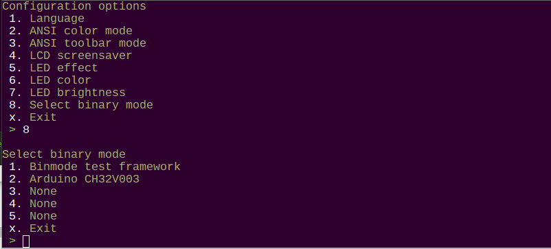
I ported this arduino programmer (debugger?) from CH32 fun project. It is super simple, so a good starting point. Select this interface from the new configuration menu → select binary mode option.
This is currently on the binmode branch. A few notes for debugging:
Not sure if this is the right byte order here or here.
This is a simple interface with bit-banged IO. You’ll need an in-line 1K resistor I guess because there is bus contention as part of the protocol.
I don’t have a working toolchain for CH32 fun, so I can’t immediately work out the bugs. If anyone wants to take a stab at tweaking the timings, please do.
Once there is a proof of concept (test bed), I will update it to use the PIO program from this project, instead of bit banging.
Edit:
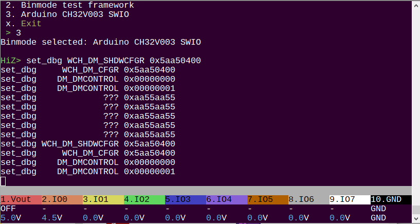
The power supply enables at 5volts because that is what the arduino program supplies.
This is now in the main firmware. Configure it with the binmode command.
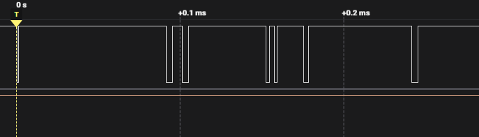
EDIT: I’ve started porting the PIO SWIO stuff from here. That will take care of all the timing. Will run it under a logic analyzer and do a sanity check.
I found picorvd pretty useful, but uart for debug console looks awful.
So I made my own version, based on pico-uart-bridge, picorvd and FreeRTOS.
In my version pico detects as two serial ports. First is console debugging, second is for gdb (flashing). You don’t need any USB–UART adapter.
I was able to wipe ch32v003 with firmware where swio pin occupied by blink example. Algo is simple: debugger must activate debug and halt chip on power on before pin been busy. Still preparing this feature.
I added command halt_on_reset that can be used when swio pin is occupied and you can’t wipe or flash ch32. It requires some action from user - reconnect VDD pin. Pico will halt execution, after that you can wipe_chip from console or flash new firmware by gdb-multiarch.
Nice! Thank you for sharing. Do you mind if I port the whole thing to a separate firmware for the Bus Pirate? Tracking your git but with the bus pirate pinouts and power supply control.