As it turns out, there are other similar boards which would be great for STEM. I found out about these:
Of course these are nothing like the general purpose boards.
As it turns out, there are other similar boards which would be great for STEM. I found out about these:
Of course these are nothing like the general purpose boards.
Adafruit has a number of boards setup for STEM projects. They even sell classroom-sized batches. Here’s one example, the Circuit Playground Express:
full Code.org CS Discoveries, MakeCode, CircuitPython and Arduino support.
Code.org Circuit Playground Express Educators’ Pack
This device is, imho, one of the best options currently available for STEM, especially if you add the acrylic Enclosure.
It’s got all the sensors, supports alligator clip connections, … and quite sturdy. Although the case is not currently offered with bulk discount, you could ask and likely get some discount for bulk order.
The second link is broken.
I am fortunate enough to have s plethora of sensors, leds, hookup wore, etc. I have a few arduino, raspberry pi motion kits (remote controlled tank, etc.)
Discovery board dev kits from back in the day as well. I need to get all of that together and check out the links provided compared to the inventory on hand to see what we could use.
Thanks for all the feedback related to my comment. Sorry if it hijacked the thread.
Huh… I just tried all three links, and all three worked for me. If it’s the educator’s pack, search on their website by that name? If it’s the enclosure, that product’s full name is: Adafruit Circuit Playground Express or Bluefruit Enclosure.
Having support for code.org / MakeCode (visual programming), and CircuitPython, and Arduino … makes for a flexible unit that can be used with various skill levels. The UF2 bootloader helps make changing functionality a breeze.
If you want one to play around with, and you’re not doing the STEM stuff for profit, send me a PM. I will send one to check out.
The link that is broken (see the second https at the begining):
Cytron Robo Pico 2
https://https/www.cytron.io/p-robo-pico-simplifying-robotics-with-raspberry-pi-pico
Not for profit. STEM/ STEAM efucation has strictly been for a small group of kids (~10 active currently) varying in age. This year the grade range varies from 3rd grade through high school freshman.
I’ve enjoyed getting back to the basics to help teach them, but I still have a lot to learn/ relearn myself. I definitely could use some guidance on how to structure and potentially get to a point where I could scale to a program that expands the opportunityto more kids in the community, but I’ve kept it small because I’m currently the only mentor (I’m not sure what other proper term would be in this setting) and still trying to figure out how best to structure a program such as this.
Thank you for your feedback and generous offer. Not only is the program currently not for profit, the funding actually comes directly from my pocket and it’s truly been difficult many times to fund such a program, even one this small. But the joy the kids get and the benefit to future genetations makes it all worth it.
Im lucky to have some lab equipment that I’m able to allow them to utilize when necessary, such as an oscilloscope, solder station, power supply, 3d printer, etc. Although, tbh I do not have anything more than a converted computer power supply and an adjustible power supply with minimal range on my soldering irom.
I’ve been surprised at the amount of replies. I would have started s different thread had I anticipated it, as not to jack the original topic of this thread. Thank you to everyone for the feedback and support!
LOL. I must have pasted/edited the post to much because it’s https://https://…
Try Robo Pico: Simplifying Robotics with Raspberry Pi Pico / Pico W
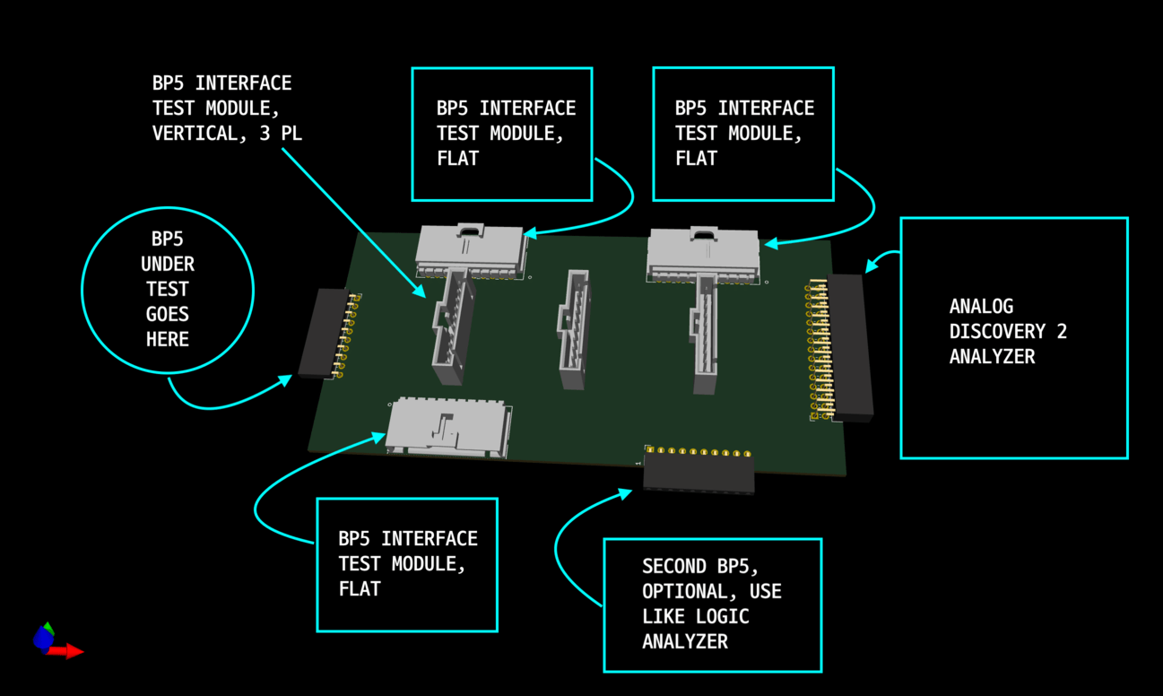
I’ve been pondering this topic in the back of my head (for what reason, I don’t know). A simple solution hit me yesterday that I think is worth considering. Instead of a big single purpose test board, that will undoubtedly be missing one crucial interface as soon as it’s ready, how about a single, small board per interface approach?
I’m imagining something smaller than a business card, or maybe say 1/2 the size of a 3x5 index card? It has the bus Pirate 10 pin connector on one side and any unique debug pins on the other. These could be used as-is, one at a time. But Tom Nardy’s recent SAO Plank project got me thinking — what if you made a little backplane that plugged into the BP5 and had a handful of parallel connected BP5 sockets?
The above mockup shows the rough idea. Maybe I went a little overboard with the number of docks. At first, I imagined vertical slots like cards in a backplane. But then I thought it could be more mechanically stable, depending on the size of these modules, if the modules were flat on the table. Why not both?
Next, I remembered listening to a recent interview with the Bald Engineer who discussed the advantage of putting a connector for your logic analyzer directly on your prototype / debugging circuit boards. It saves a lot of effort moving clip leads. With this in mind, I added an Analog Discovery 2 connector on the opposite end of the board, and also added another plug for a second BP5 which could be used as a sniffer if the full capabilities of a logic analyzer aren’t needed.
There is no end of module possibilities, but many of them have already been discussed here. The nice thing about such individual modules is that they are going to be really cheap to make or buy. You could even make blank boards with prototyping grids, common sockets, or even a small breadboard. A hobbyist could just keep a handful of blank boards and solder them up as needed. Ian could use them to test and develop all kinds of interesting and new interface modes. For factory production, of either the BP5 or other simple products, the connectors can be replaced by just soldering the modules on the bus plank (so the factory can’t goof it up).
Anyway, this is just an idea. Once I finished the mock up, I already am having thoughts about how to arrange things differently. but the overall concept is the same.
I like the idea. There are standard connectors for STEM projects, like Grove, STEMMA, PMOD as well.
I should mention that I use the quick-connect KF141 adapters, extra long male header pins, and a stripboard to prototype quick-connect test jigs. It’s easy to slide the header pins into the KF141’a and solder them onto the board. And if you don’t have enough KF141’s, it’s easy to switch the PCBs. That is, until someone starts selling BP proto boards (blank planks).
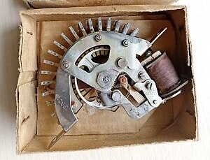
Reminds me of these universal JTAG adaptors
Well, my thought was to use the exact BP5 connector family. This way one doesn’t have to use the backplane, but could just plug the module into the BP5 directly. But one could make a module that did just had one or more of these common interface connectors, and that way you could easily test with existing widgets.
Those JTAG adapters can be really helpful. I have still managed to back myself into a situation where the one JTAG connector I needed was not on the board. I’m thinking of one case when I was using one of those ST extended connectors (that has serial port signals on the ends of standard JTAG, I think it’s a 2x7 vs the more common 2x5)
Does paralleling several BP5 sockets work?
The goal is to have several planks connected at the same time, so you can easily test the firmware to access them without physically replugging, correct?
So let’s say you got several different flash IC connected in several flash-socket planks (DirtyPCBs.com). Then the output pins of the flash ICs are connected in parallel and would clash. Other planks will probably run into similar issues.
I think you’d need some kind of analog mux in between instead of paralleling them to make this work. For example NX3L4051 or other 4051-variants work well as they have a 8-to-1 interface. But you also need a way to control the mux and tell it which channel to activate. You can’t do this with the main BP, as you’d need 3 pins to switch between the 8 channels. Many planks will need all 8 data pins of the BP interface, so you can’t just hardwire 3 of them to the muxes.
So you’d need your second BP (or some other microcontroller, could be as simple as a Raspi Pico you solder onto the board) to select the muxes. I also suggest a power switch for the Vout, as not all planks might like all voltages.
For testing I do like the idea of a bank of 20ish bus pirates hopefully connected via usb hubs to an rpi or whatever the cheap orange pi is these days. I can make it a listener to a rabbit MQ or something and pass tests down the queue from the build server. If they’re all BP6 then we can return the logic analyzer capture of each test too which is just silly cool.
Then I can make a website that has full debug info with browser based trace viewer, but that would put me in the PHP code mines and I’m trying to avoid that because PHP and I had a falling out.
Yeah, I thought of MUXes also. But mainly the reason I thoighy just a passive backplane was for development testing, a situation where you might use I2C on one module and say serial or SPI. Not situations where you’d have overlapping interfaces. When I was testing my MicroPython modules recently, I was switching back and forth between a UART (serial to USB) interface and an SPI EEPROM. And also wanted to test just general purpose but banging. In that case, I could’ve used three modules, UART, SPI, and bit banger. And I also imagined a module just to bring out the VREF to banana plugs for a DMM and an BNC for oscilloscope observations. Now maybe that’s a rare situation, but I could have used four modules in parallel.
Ian brings up a good point about factory testing of multiple BP5 units at once. That would certainly need different connectors, and a MUX would come in handy. But, you could conceivably use the BP5 to cooperatively MUX themselves in such a scenario (although addressing would be a fun challenge)
It’s tester setups like this where you wish the old telephone exchange ten position stepper relays were still commonly available.
Ian, point well taken about the BP6 as a logic analyzer. That thought had occurred to me as well. BTW, what logic analyzer do you and the dangerous team use in your development efforts? I’m curious what folks use typically these days, where you have everything from the bare minimum $5 AliExpress module + Sigrok, the few hundred dollars Analog Discovery, and the kilobuckish Seelea. (My first exposure to a logic analyzer as a young engineer was something the size and weight of a piece of carry-on luggage, costing who know how many thousands of dollars. )
But then you’d have to design the planks in a way that their pins don’t overlap. This would be a quite limiting design decision. And you’d just be able to mix some and not others - not really easy to figure out and documentation minefield.
I think just using jumper wires instead of a ready-made backplane looks more viable to me for this usecase. Because then you aren’t fixed to the pin positions the plank designer originally selected, but are able to re-route them as needed to make them compatible.
The cheap FX2 based logic analyzers get me quite far actually - because they are able to constantly stream with 480 MBit/s into the gigabytes of ram of your PC. If this isn’t enough, I use the one integrated into my scope. It is much faster, but just has a limited buffer, so correctly triggering becomes quite important and sometimes difficult, for example with a digital protocol your scope doesn’t have a decoder for.
I use a $3 delivered old saleae compatible from Ali. I had the original saleae but it kicked the bucket a few months ago.
However, with the patched PulseView working well on Windows, and the bus pirate logic analyzer updates, I am starting to use the BP6 logic analyzer, and also the internal logic analyzers on 5. The logic graph in vt100 is kind of dumb, I know, but it gives a super fast overview of what happened and I find myself using it a lot when developing.
Noted. In my initial thought process where I was imagining a UART, SPI, bit banging, and VREF, they all use the BP5 pre-defined pins for those respective functions. That’s why I didn’t initially think about a MUX or jumpers. But also I was thinking that the case where someone needed multiple modules would be quite rare, short of factory development and testing.
Certainly MUXing is a great idea. Or a row of jumpers for a lower cost solution.
Thank you @henrygab!!!
The next time I believe we are getting together should be this Saturday, I need to check the calendar. That gives me a few hours to walk through the links you provided beforehand.
Again, your generosity is greatly appreciated, and the kids are excited to find out more about it.
For anyone else looking for a good STEM starting point, here’s some reasons why I like the CPX (Circuit Playground Express). To keep the thread vertical height reasonable, I’ll hide in details blocks, so expand only if interested…
There’s a full-blown in-browser simulator, support MakeCode’s visual (aka block) programming. The same website can do a one-time translation to Javascript for more precise or complex control, if desired. When done, the website can convert that program (visual or javascript) into a compiled binary .UF2 file … allowing to run the program on a physical CPX device. It feels like magic the first time one does this…
Bootloader shows up as a mass storage device. Unlike the pico (which is write-only), the CPX also exposes the current firmware as a .UF2 file, so you can make a backup at any time. This makes it easier to share devices among students.
There’s a ton of built-in peripherals (mic, accelerometer, IR TX/RX, light sensor, two buttons, slide switch, 10x RGB addressable pixels, 1x LED, …), while still exposing a bunch of pads for external components. Those exposed pads are large holes, making it easy to poke at with a multimeter, alligator clips, or even shennie-style hooks … no soldering required.
A good case greatly increases the value, imho. This case allows access to all the edge contacts with alligator clips, and even includes a 1/4" threaded hole on the bottom (e.g., for camera tripod). Not bad for an extra ~$5.
Easily swap modes:
.UF2 file to run the program on a real deviceFirmata firmware allows PC-side code to control the device (from many languages)
Avoid wasting time re-inventing the wheel. Free curicula from code.org and creative projects abound.
Code.orgcode.org uses Firmata firmware to directly control the CPX device from the PC (e.g., via Python).
https://code.org/maker#curriculum-link-cphttps://studio.code.org/s/devices-2024?viewAs=Instructorhttps://studio.code.org/s/focus-on-coding4a-2024?viewAs=InstructorCircuitPythonCircuitPython is a variant of MicroPython, and Adafruit provides a lot of libraries to reduce the complexity of labs using the CPX.
.UF2 file from:https://circuitpython.org/board/circuitplayground_express/https://learn.adafruit.com/circuit-playground-express-circuitpython-5-minute-guide/update-circuitpythonhttps://learn.adafruit.com/circuit-playground-express-circuitpython-5-minute-guide/upload-codeFor DIO testing, you have four states that each of the eight main pins can be in:
I don’t think 8 LEDs and switches allow testing eight pins for all eight states.
I’m not 100% sure of the result of step 2 / step 4
The BP5 could alternate which set of four pins are input vs. output. (e.g., DIO0…3 vs DIO4…7; or DIO0,2,4,6 vs DIO1,3,5,7).
Repeating four times the following circuit, with DIOx from one set, and DIOy the second set of exposed DIO:
       /----------<LEDr<---------\
       |                         |
DIOx --+-->LEDg>---GND---<LEDy<--+-- DIOy
       |                         |
       \---------->LEDb>--------/
(LED resistors ommitted for clarity)
Meanwhile, the program running on the BP5/6 would do something such as:
The color and placement of the LEDs (and how you group them) will define how beautiful the plank is when used for testing. However, it should be quite simple to visually verify each phase.