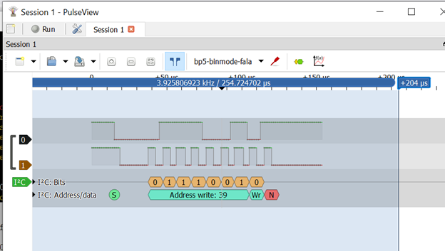
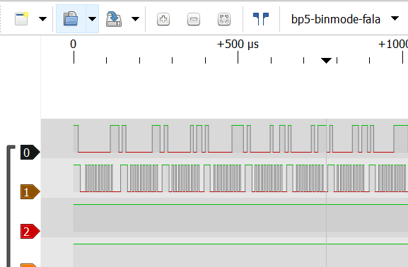
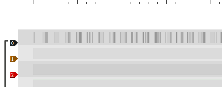
You have to manually select a device in Pulseview it doesnt auto pick buspirate and also make sure to enable fala before in text console of BP5 and choose binary port in Pulseview
I compiled your repo no problem. I then installed the libraries.
But I need pulseview. If I tried to installed it via apt, it wants me to install the official sigrok libraries - which overrides the patched libraries I just installed.
If I compile pulseview from the github using the patched libraries, I get errors.
If I install pulseview from apt (synaptic), it overwrites the libraries, and when I start pulseview I get errors:
pulseview: symbol lookup error: pulseview: undefined symbol: _ZN6sigrok7Context20create_analog_packetESt6vectorISt10shared_ptrINS_7ChannelEESaIS4_EEPfjPKNS_8QuantityEPKNS_4UnitES1_IPKNS_12QuantityFlagESaISG_EE
I’m missing a step.
Ow yeah I just installed pulseview from apt and then replaced symlinks to libsigrok and I think one more libsigrokdecode? Something like that with the ones compiled. If you installed them in the same directory as normal system libs then purge everything reinstall pulseview from apt/aptitude and make install compiled libs to /usr/local/lib so they wont overlap with the system. Let me just find the exact commands in bash history
EDIT:
ln -sf /usr/local/lib/libsigrok.so.4.0.0 /usr/lib/x86_64-linux-gnu/libsigrok.so.4
ln -sf /usr/local/lib/libsigrokcxx.so.4.0.0 /usr/lib/x86_64-linux-gnu/libsigrokcxx.so.4
ln -sf /usr/local/lib/libsigrokdecode.so.4.0.0 /usr/lib/x86_64-linux-gnu/libsigrokdecode.so.4
Your directories might differ depending on your architecture of course. If you need help reach me via chat/DM ![]()
Still digging into this. Scanning at 100Khz works. 400Khz doesn’t.
I’m seeing two problems.
- When I copy the individual bus commands as described in the demo, I get NACK’s. Here’s what happens with the first one (below).
- When I run the script attached, and start the logic analyzer just before the pause command, nothing shows up.
Here is the first NACK I get,
I2C> [0x80 0xf5] D:23 [0x81 r:2]

I2C START
TX: 0x80 NACK 0xF5 NACK
I2C STOP
Delay: 23ms
I2C START
TX: 0x81 NACK
RX: 0xFF ACK 0xFF NACK
I2C STOP

I2C> i

[snip]

Bus Pirate 5 REV10
https://BusPirate.com/
Firmware main branch @ unknown (2024-11-27T14:01:41Z)
RP2040 with 264KB RAM, 128Mbit FLASH
S/N: 32104F0B33CC62E4
Storage:   0.10GB (FAT16 File System)

Configuration file: Loaded
Active binmode: Follow along logic analyzer
Available modes: HiZ 1-WIRE UART HDUART I2C SPI 2WIRE DIO LED INFRARED
Active mode: I2C
 I2C speed: 100 kHz
 Clock stretching: OFF

Display format: Auto
Data format: 8 bits, MSB bitorder
Pull-up resistors: ON
Power supply: ON (3.3V/3.29V)
Current limit: OK (4.8mA/0.0mA)
Frequency generators: OFF

1.Vout  2.IO0   3.IO1   4.IO2   5.IO3   6.IO4   7.IO5   8.IO6   9.IO7   10.GND
4.8mA   SDA     SCL     -       -       -       -       -       -       GND
3.3V    3.3V    3.3V    3.2V    3.2V    3.2V    3.2V    3.2V    3.2V    GND
And here is the script I am using.
si7021.txt (226 Bytes)
But does FALA work for you now? Remember to arm the capture in Pulseview before executing commands
I used pulseview on Windows today.
I was getting undefined symbols on Linux. But I only installed two shared libraries. I’m going to see if I have everything I need to compile the decode library - perhaps I am missing some prerequisites and this will check if that is the case.
But I’m on holiday duty today. No debugging. If you are in the US, have a great Thanksgiving. If not, have a great day and thanks for asking.
But the problem I was reporting on was using the FALA and the script I attached.
I ran the script up to the pause command, then started the capture, and then continued the script. The FALA showed nothing.
But if I do a scan, it shows pulses. The script - no pulses.
Is FALA mode enabled? It should tell you how many samples were captured after each operation:
INFRARED-(RC5)> >0x3010

TX: 0x3010.16

Logic analyzer: 7753 samples captured
INFRARED-(RC5)>
And then Pulseview will just automagically update.
Use the binmode command to enable the FALA interface, then setup Pulseview and click run. You shouldn’t have to do anything else.
I have the FALA running (Windows + BP5). I’ve seen several strange things. Here’s one thing I see
I2C> tsl2561
Read light intensity (LUX) from TSL2561 sensor
ID: 5 REV: 0
Chan0: 214 Chan1: 72 LUX: 58Logic analyzer: operation too long, buffer invalid
Here’s a second problem while testing the light sensor
I2C> tsl2561
Read light intensity (LUX) from TSL2561 sensor

Logic analyzer: 123 (0x0000007b) samples captured
Note that no results were printed. Pulseview showed
Please update to the latest firmware. It now shows the beginning if the buffer instead of giving that error.
That makes sense, that’s a nak. I can add an error there.
A third problem I see is, without changing my hardware setup, I do an i2c scan and sometimes I get:
Error: Pull-up not detected on IO pin.
I repeat the scan and it works.
I’ve a breadboard with the two sensors (tsl2561 and si7021). I’ve used the same hardware for months and the demos worked fine then.
Thank you for all the extra info, the fala shot is super duper helpful.
In a recent update I changed how pull ups are detected in all mode and I may have made it too strict in i2c. I’ll look at that. It was that only one pin had to be high, but now it wants both high at start. Which is not really helpful so I’ll loosen it up.
So what’s happening is the chip doesn’t ACK the final bit during the tsl program, then it aborts and the clock line stays low. I’ll update it to give an error and issue a final stop to reset the bus.
Is the FALA image from a 5 or a 6? A 6 is much more useful for this because it has the extra buffered inputs so we really know what’s happening on the bus.
It’s from a 5. I’ll switch over to a 6 when I next check.
I installed today’s software on a BP6.
New Bug:
The “logic” command appears to do nothing.
HiZ> binmode

Select binary mode
 1. SUMP logic analyzer
 2. Binmode test framework
 3. Arduino CH32V003 SWIO
 4. Follow along logic analyzer
 5. Legacy Binary Mode for Flashrom and AVRdude (EXPERIMENTAL)
 x. Exit
 > 4
Binmode selected: Follow along logic analyzer

Save setting?
y/n (Y) > y


Logic analyzer speed: 0Hz (8x oversampling)
Use the 'logic' command to change capture settings

HiZ> logic

>
type or paste code here
Try logic -h to see the options. I’ll add the auto help there too, sorry about that.
Fixed the blank output when using the logic command with no options. It now displays the help output. A variable wasn’t being initialized correctly.
I will add error output to the TSL demo shortly.
Pushed a few fixes:
- I2C demos all report errors on fail
- Attempt to reset the I2C bus with a STOP on error
- Made the pull-up check less strict (now identical to old behavior). This may need further tweaking, not sure it was a good idea to run it globally at the start of any syntax. For 1-wire and I2C it is probably better fixed to only the START/RESET commands to avoid error reports when splitting commands over multiple lines.
As you may recall, I was having trouble repeating the device demos. I have identified one of my problems. While debugging this, I used 3 different BusPirates:
#1 = BusPirate 5 Early Release with 1 of the two mods
#2 = BusPirate 6 with modded resistor (I Fixed My 6)
#3 = BusPirate 6 replacement.
Test condition: same hardware sensor. Same BP software configuration. Same firmware version. I simply unplugged the test connector from one BP and plugged it into the other. I then set up I2C mode and did a simple I2C scan.
Problem identified: BusPirate #2 was not generating clock pulses. Here is the screen dump when using BP #3:
And here is the screen dump while using BP#2
And this is the configuration of BP#2. It passes self check.
I2C> scan
I2C address search:

Logic analyzer: 26431 samples captured

Found 0 addresses, 0 W/R pairs.

I2C> i

<snip>

Bus Pirate 6
https://BusPirate.com/
Firmware main branch @ unknown (2024-12-08T14:49:21Z)
RP2350B with 512KB RAM, 128Mbit FLASH
S/N: 9AE9C5C4AD757FE7
Storage:   0.10GB (FAT16 File System)

Configuration file: Loaded
Active binmode: Follow along logic analyzer
Available modes: HiZ 1-WIRE UART HDUART I2C SPI 2WIRE DIO LED INFRARED
Active mode: I2C
 I2C speed: 100 kHz
 Clock stretching: OFF

Display format: Auto
Data format: 8 bits, MSB bitorder
Pull-up resistors: ON
Power supply: ON (3.3V/3.29V)
Current limit: OK (3.6mA/0.0mA)
Frequency generators: OFF

1.Vout  2.IO0   3.IO1   4.IO2   5.IO3   6.IO4   7.IO5   8.IO6   9.IO7   10.GND
3.6mA   SDA     SCL     -       -       -       -       -       -       GND
3.3V    3.3V    3.3V    3.3V    3.3V    3.3V    3.3V    3.3V    3.3V    GND
I am concerned that the BP was broken, yet passed self-check.


