That is pretty fancy for a cable testing, I used this to measure cables you can find them off ebay since they are on backorder but it also helps with other things. Non-Invasive Current Sensor - 30A - SEN-11005 - SparkFun Electronics
![]() Different purposes in this case. But valid point. This is a nice find for the price though. The “amp clamp”, that is.
Different purposes in this case. But valid point. This is a nice find for the price though. The “amp clamp”, that is.
Sidenote: I think we need an off topic section with a thread just for helpful links, tools. Etc.
I agree on the tools topic, its relevant especially tools that work well within the buspirate ecosystem. i have been taught that once i get far enough with my general boards then i will break out into something else. but its also super appealing with the plank system. for instance, i own a analog discovery, its nice i use it to read data coming from their Analog Discovery Audio Adapter+. that is what i use to read the data from those clamps. in fact using that when doing anything usb, you get interesting data. fingerprinting almost.
If anyone is looking for USB testing jigs, here’s a couple of low-priced items people might find useful.
- USB pcb adaptor - just an easy way to tap into a USB device at the hardware level. I’m not sure what happens at high speeds.
- Alvaro Prieto’s USB cable tester - this is just a cable continuity tester but the LED’s identify which lines are present. Since it’s open source, you can build your own or order it on Aliexpress. Here’s one link. I have mixed up cheap and expensive cables, and this helps me sort them by capability.
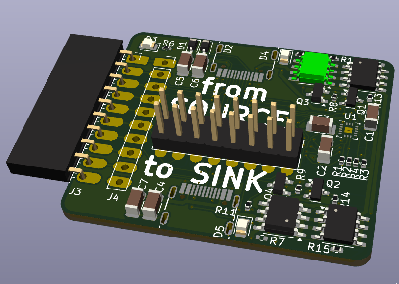
Have just sent a pcb off to JLC for this. Had to use standard assembly because the pin pitch on the qfn is 0.4mm. Let’s see how we go.
Am targeting USB-C PD
- Sniffing
- Source Emulation
- Sink Emulation
HS pins are n/c, signal quality on usb 2.0 will be meh. These things could be improved.
Header in the middle will be filled with shunts to allow isolation between the two connectors as needed.
This looks fantastic, very excited about the USB cable chips.
This is plank form factor so I’d be happy to send it to our assembler. Similar to the PS/2 and USB sniffer plank @dreg is playing with.
Thanks Ian. I’m going to pay for the first prototypes, I’m ok for money but my time availability varies a lot. Once I’ve proved the electricals I’ll try to send you some. Planning for you to own the final plank design if it’s worth that.
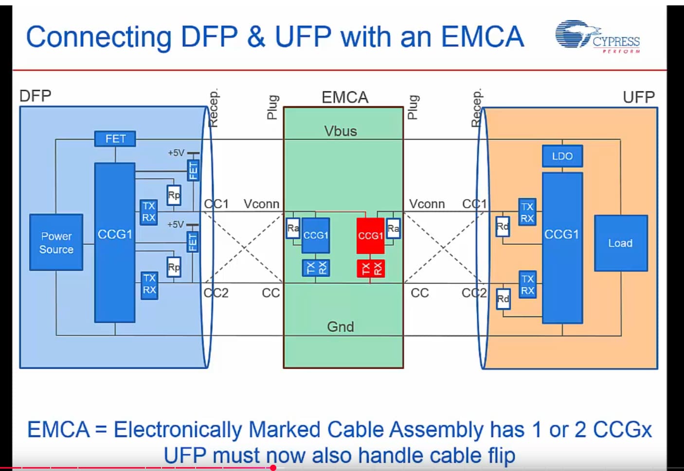
This is video is long and a little slow but a good backgrounder on PD. https://youtu.be/V1OiQoyjDOo?si=RGDN01RFG-XckyAu
Marked cables are part of the source emulation stuff. It’s a neat design, there are two CC pins, one serves as the power source for the chips in the cable, the other as the comms channel. Since the cable is reversible the role can be played by either pin depending on orientation. Am still learning all this but I seem to have the right chip and I’ve copied most of the circuit from the (EOL) eval board so I think this will work.
He says he’s been involved in USB since the beginning in 1995, 20 years ago. I thought, that’s not right, but then I scrolled down to see the video is 10 years old ![]()
I find the gap between innovation and adoption really interesting. This stuff isn’t new but now that we’re all carrying devices that need 35W+ to change in a reasonable time it’s getting a lot of use. I was reflecting just yesterday on how 240w over a usb cable seems so extreme - my measure is how hot 200w light globes used to get.
(I have one of his original usb books somewhere, he knows his stuff).
@ian am digging into the code. I need to run i2c within my mode. As far as I can tell there is currently no way to configure i2c except via the TUI.
Are you ok if I add methods like hwi2c_set_speed() ?
Have a look at hwi2c_pio.c, it provides the basic low level functions for working with the PIO I2C program that manages the IO buffer direction.
void pio_i2c_init(uint sda, uint scl, uint dir_sda, uint dir_scl, uint baudrate, bool clock_stretch)
This setup includes the pins to use, the speed, and if you want clock stretching.
Of course add all the functions you want as well ![]()
@ian I wonder if it’s worth exploring e-marking planks? Seems like a lot of them would have a pin spare, a per plank resistor divider and an ADC measurement would be an easy way to sense a plank and autoswitch to the right mode (using a new command).
As someone who regularly fights with e-marking, I heartily support this idea!
The idea of a side channel has come up a few times. Usually in the context of a 1-Wire ID or similar.
Using a resistor divider on any free pin and scanning through them is interesting though. It doesn’t depend on a constant free pin, which is the main problem (pins move around).
The new plank finder command could also accept a 3 or 4 character code that we print nice and large on the PCB.
So the idea would be to first enable Vout and then look at all pins that have a voltage != GND && != Vout?
That would mean we’d have to enable Vout without the autodetection mechanism, so you can’t know beforehand which Vout is safe for the plank that is plugged in. And at least until we have the full Vout protection implemented as planned for BP8 we can’t just enable pullups but keep Vout off otherwise.
But let’s assume enabling Vout is ok.
Now you know for each of the e-marked planks that there must be some known voltage (± tolerance) on one known pin.
Isn’t this a bit too loose of a spec? I mean you could have an analog sense / opamp plank where most pins are analog in. This would throw off this mechanism as it could easily be detected as some different plank.
We don’t need a 100% failsafe mechanism, but just one voltage seems a bit too error prone to me. I would prefer to combine two criteria before declaring a match.
Maybe we could combine a voltage divider with capacitor and/or diodes to give a port an unique pattern that can be sensed. I would prefer to not need additional pins.
I think a nice future solution would be an NFC reader with tags on the planks.
Several times I’ve looked into it. The antenna loops are usually really big, and there’s no PCB mountable module with FCC CE etc like there are for wifi and Bluetooth. Which blows my mind because tap and pay is so common these days.
yeah, the FCC CE and antenna stuff is what makes building your own expensive. This is common tech, but not on microcontrollers. It is one level up, things like smartphone procressors and more complex embedded things like payment terminals, smart locks with internet access and the like.
Regarding the detection with an E-marker like thing:
we could make just the initial pin detection based on a voltage divider. This tells the BP: hey, there could be something on this pin, go test it. The BP then carefully enables/disables it’s pullups on this pin in a special pattern. On the pin we don’t have just the voltage divider, but a small & cheap microcontroller. You can communicate with it just by enabling the pullups on the BP. The microcontroller then can switch on and off the voltage divider. This way you never pull the pin hard to Vcc or GND and don’t risk destroying something if there is no actual E-marker on this pin.
Regarding microcontrollers, the cheapest solution would be:
These are tiny compared to regular modern microcontrollers you are used to. Also only one-time-programmable. But for this kind of application this shouldn’t be an issue. They are 5V capable which I consider important here. There is a full open toolchain and the programming protocol has been fully reverse engineered and documented. Search for it on the eevblog-forum.
I have a few hundred of these on cut tape here and played with them. It was nice going back to such a super reduced controller and still being able to squeeze reasonable features out of it. I used them successfully on one project as voltage supervisors to implement a more complex voltage rail enable/disable pattern. And on another project to communicate reed sensor state from many reed sensors over just one wire with limited space.
Downside is that you would need a small separate programming pin header on the plank and program the controller over it for each plank.
If you prefer a more common architecture and don’t want to break the bank or allocate much space, these would also be an option:
This is quite common ARM Cortex-M0+ fare, regular flash, programmed via SWD. Also 5V capable.
It has the advantage that you don’t need any addiitional toolchain, as the same arm-none-eabi-gcc as for the BP could be used. And someone else building their own planks wouldn’t need the special programming hardware to program the Padauks, but could just use their BP in SWD mode to flash the Puya.
But about 5 times as expensive as the Padauk ![]()
I like it all! Some of the planks are pretty low volume and with a clock on the board we have to FCC and (extended) CE every board. That’s just not in the budget.