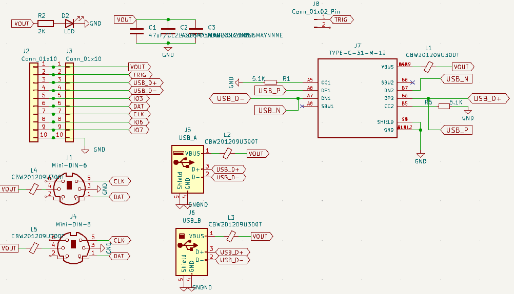
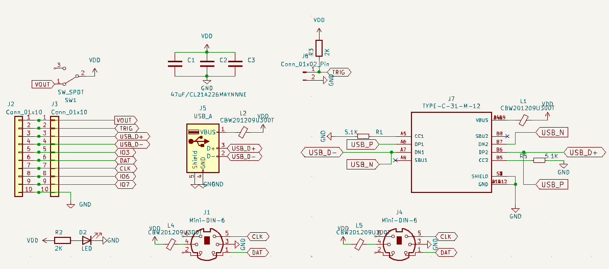
2 or 3 Samsung CL21A226MAYNNNE - @electronic_eel suggestion (I’m using 47uF TAN in the prototype)
SWITCH:
Physical sliding switch to connect the VOUT from the Bus Pirate to the VCC of both PS2 and USB
Connectors:
I prefer through-hole (TH) connectors for TRIGGER PIN, USB and PS2 because they withstand the test of time better. (Many times with SMT, I’ve ended up with the connectors in my hand when connecting extension cables, etc.)
This is going to be used to connect the plank to the PC, for example when doing USB sniffing, correct?
I think it is mechanically not sound to connect a USB A male plug that has a plank and BusPirate hanging off it directly into a PC. So the only option here would be to use a USB-A female to male extension cord and connect that to the PC.
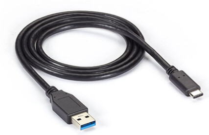
While these USB extension cords are common, I think they aren’t as common as, say USB-A male to USB-B, micro-B or USB-C.
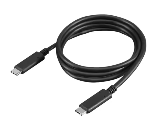
So I suggest to just use a USB-C connector here. These are getting more common every day and also there are well-designed SMT versions available that are cheap&easy to manufacture while still being mechanically robust. Look for example the one that is on the BusPirate. I would suggest using exactly that part.
This is in line with my thinking about it. If you must, a big chunky B. But in reality a small low profile C is probably enough on its own. “Everyone” has a phone charging cable.
Is this needed? If the PC is providing power, then the Bus Pirate buffer should be powered by the PC. If the keyboard is stand alone with the Bus Pirate, then the user hits W 5 to power everything?
That makes sense. USBC SMD is very strong though, it has the partial through hole mounting posts that can be stenciled and reflowed.
I like using USB Male-A because it allows connection with a simple USB Male-to-Female extension cable.
And if that cable ever fails in an urgent situation, the standalone USB-A Male connector can still be directly plugged into a PC somehow.
(I know it’s not ideal, nor a great idea, but it could save you on a bad day.)
Anyway, just go ahead and use USB-C instead.
Don’t use Micro-USB or anything else—I think USB-C is the best choice.
I still prefer through-hole (TH) options, but if it’s a matter of manufacturing and cost, use whatever works best.
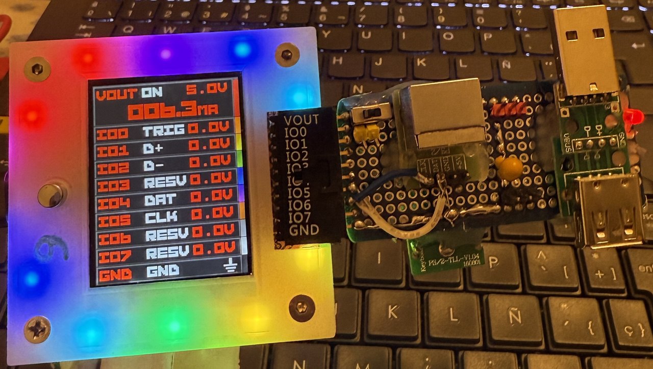
The trigger PIN is for USB—connect it directly to IO0 on the Bus Pirate. We’ll use it to let the user start capturing via external signal. Since in USB Full-Speed, memory will fill up quickly, and we can’t sample too many packets, this gives the user more control and allows them to use an external trigger to start everything. I placed two pins to make it easier to solder without using tweezers and burning myself, but you can use just one pin there. Although keeping it straight and aligned with just one pin can be tricky.
Some PS2-to-USB adapters are garbage and behave strangely, so I like the idea of manual thing to isolating the Bus Pirate’s VOUT from the target device’s power supply + having the option to use it when needed, to provide a bit more milliamps to the target.
Also, keep in mind that you might be sniffing on one PC with the Bus Pirate, while the target keyboard is connected to another PC, which could have a slightly different USB voltage.
In fact, for USB sniffing, it’s very common that the sniffing PC and the target PC where the USB device is connected are different, The goal is to avoid saturating the USB bus. Having all the USB devices from the target PC + the sniffing tool on the same USB host is usually a bad idea.
NOTE: USB sniffer isn’t just for keyboards—this is a sniffer for any USB device up to Full-Speed , including USB Mass Storage Full-Speed etc.
But maybe I’m being too paranoid—if you think this isn’t necessary, feel free to leave it out (slide SWITCH).
I’ll update the schematic now that the design is stabilized.
TVS diodes are a bit of a stretch I think. They should be on the target and the host PC (and the Bus Pirate…), Probably not needed on a vampire tap. Even the ferrites are overkill, but you mention noisy adapters and there are long powered cables involved so it might in some cases reduce power noise.
Didn’t realize who I was replying too, sorry. You didn’t mention the noise
PS/2 is powered with 5V and IIRC it also uses 5V for data. So set VOUT to 5V and everything works.
But USB uses 3.3V as voltage on the data lines while Vusb is 5V.
So pure sniffing of USB with VOUT set to 5V might not have the correct threshold levels on the 1T45, but I think it should still work.
The real issue is when you want to translate between PS/2 and USB. Then you need VOUT set to 5V for the PS/2 part. But when you write on the USB data lines, you use a too high voltage. This poses the risk of damaging the host or device you are talking to.
I don’t see another solution than adding a 3.3V regulator and two 1T45 to the plank to fix this. But the direction pins of these additonla 1T45s will have to be driven, changing the code from @Dreg