USB Sniffer & PS2 Sniffer Plank + Firmware for BP

These slider switches are also available with 4 positions:

I didn’t see one like this from Shou Han, but maybe this just isn’t listed at LCSC or the data for the parametric search not entered properly like ever so often.

This would allow to switch in the proper 15k pulldowns for host mode:

  1. Sniffing (no resistors)
  2. Host mode (pulldowns to be able to detect the device’s pullups)
  3. Lowspeed Device
  4. Highspeed Device
2 Likes

With the VOUT selection we can do the IOs at 3.3 while letting the 5v pass through? It does require awareness of the user.

Speed will be /4 with an extra bidirectional buffer and I don’t know enough to predict the effects of that.

When using the Plank as a USB Host, we need to provide 5V to the device, but for data communication, we must send 3.3V on the data lines.

2 Likes

Got it, a host thing.

1 Like

Without the 1T45s we can’t do PS/2 and USB at the same time, so no kind of translation. And the user would have to be careful to disconnect the VOUT switch when doing USB.

Also the pullups the USB device requires go to 3.3V, not to 5V. But then we wouldn’t easily have 3.3V on the plank. So we’d need a 3-way switch for VOUT to be able to connect the VOUT from the BP to the pullups on the plank, but disconnect the 5V Vusb from VOUT.

And then you’d need to plug in external 5V when you want to be USB host, because you have to provide power to the device. With the voltage regulator this wouldn’t be necessary.

Isn’t the speed of the 1T45 in the order of like hundreds of MHz when doing 3.3V and 5V? This shouldn’t limit a fullspeed usb which is 12 MBps.

2 Likes

The PIO takes several cycles to switch buffer level and direction, then add XIP overhead, then add firmware latency to change the the secondary direction. That is not to mention buffer speed.

I’d not want to be the guy bringing that up. I am very cautious about such things though and if you all want that hardware it I will try to make it happen.

Well… in the worst case, we’d be stuck with Low-Speed Host? That’s still better than nothing!

Let’s test a first version with these changes and evaluate it once we have the Plank in hand, after testing with an oscilloscope, etc.

Sure. I wasn’t aware that full speed host and device are possible with PIO at all.

Are you aware of any other projects doing fullspeed host/device on an RP2350 or RP2040?

Maybe you can take a look at their code to evaluate how hard it would be to adapt that to something with two levels of 1T45 in between.

Just so that you get an impression of how complicated it will be and if the second layer of 1T45 will be the thing that breaks it or not.

Layouting, manufacturing and shipping the plank to you will take ian some time, you probably don’t want to need an additional roundtrip of that due to a bad design decision that could have been avoided by something like an hour of searching.

2 Likes

NOTE: I have no idea about this project and have never used it in my life. :sweat_smile::joy:

2 Likes

Actually, that’s the project I was going to post about today. I’d been following that project since it wasn’t even feature complete.

I intend to use that project as the USB basis for a small project I’ve planned … basically providing a testing framework for the Xbox Adaptive Controller by providing scriptable inputs … because the XAC supports two USB HID joysticks for inputs, and this can be emulated using a single RP2040 (don’t even need a RP2350).

So, while I’ve not used it yet, it’s the best thing I could find with much searching.

3 Likes

So, are we all in agreement on this for the first Plank prototype to review hands-on?

I’ll recap everything we’ve discussed… Let me know if I missed anything!

FEATURES

:white_check_mark: Sniffing PS/2 and USB (low speed and full speed)
:white_check_mark: Pure USB device
:white_check_mark: USB Host OTG
:white_check_mark: PS/2 Keyboard → USB Keyboard (pure PLANK conversion)
:white_check_mark: USB Keyboard → PS/2 Keyboard (pure PLANK conversion)
:white_check_mark: no pure PLANK conversion scenarios via Bus Pirate’s USB-C composite device

FIRMWARE COMPATIBLE

(With modifications)

Proposed PCB Changes

Starting from the latest design shared by @ian.

  • Add an additional position slide switch to set the speed (PURE PLANK USB DEVICE). We simply leave the Full-Speed or Low-Speed resistors on the data lines, depending on the switch position.
  • Add a 3.3V regulator and two 1T45 to the plank (D+ and D- ). The direction pins of these additonal 1T45s will have to be driven via BIO6 and BIO7. With this, we’ll have bidirectional communication on the USB data lines without any issues.
  • Add the very low pulldown approach to sense the state of the lines

Do you see any compatibility issues with the Pico-PIO-USB project?

Resource Usage

  • 1 PIO, 3 state machines, 32 instructions
  • Two GPIO for D+/D- (Series 22ohm resitors are better)
  • 15KB ROM and RAM
  • (For Host) One 1ms repeating timer
  • (For Device) One PIO IRQ for receiver

Do you see any issues with this? Any suggestions for improvement? @ian @electronic_eel @henrygab

2 Likes

I don’t know enough to provide meaningful input as to whether the IT45 would be problematic for the Pico-PIO-USB project.

Someone would have to look into how it transmits / receives data … My guess is having additional components needing to be flipped during operation would be incompatible … the PIO state machines were really, really tight last I looked, and any changes might be significant / break into needing more PIO, for example.

Personally, I think it might be better to split out the USB host & device options into its own plank, so that project can be used essentially without change. It could also provide up to four (!) additional USB ports, if I understood correctly, since only need two adjacent IO per USB port.

2 Likes

Running it on the BP would already need changes to it, because this code is designed to run on raw IOs of the RP2040. But the BP always has one layer of 1T45 level shifters in between. So the code of the state machine should be checked how such a change would be possible.

With PIO it sometimes is important how the IOs are ordered, if they are directly next to each other and so on. This is something we could influence with plank design and should check for now.

Nope, intrusive change required, see above.

Combining it with the PS/2 as planned here would allow translation to/from PS/2, which wouldn’t be possible with a pure USB plank.

A pure USB plank with multiple ports might, depending on the software capabilities, allow some kind of meddler-in-middle translation capabilities for some kinds of USB devices, like HID tough. Like replace one keypress with another or add macro capabilities to dumb keyboards. This also sounds interesting. But I’d start with PS/2 translations first, because it is the more basic protocol.

2 Likes

I’ve lost track of this discussion, but I very much would like to get a prototype made.
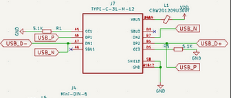
USB C

We do this cross connect of USB_P and USB_N, which I understand was needed to tell the USB host that we are USB 1.0 or 2.0 device.

SparkFun does it differently, but their connector is only 6 pins so maybe the connections are made internally.

  • I’m not sure if it is something to be concerned about.

PS/2 sniffing

Sniffing is tested. In sniffing mode the Bus Pirate is a passive listener and the IO buffers are input. The bus is 5volts and the power is 5volts.

  • This seems fine

PS/2 Host

@Dreg have you managed to test this on the Bus Pirate through the IO buffers? It will be different than using a bare pico.

PS/2 is a bidirectional, open drain protocol where the clock is always provided by the device.

The program should be structured like I2C.pio: Enable GPIO pin pull-down (on 5, 6 has the big pull-down to fix E9), then manipulate the IO buffer direction pin between input and output to release or hold low the bus.

Input should be read from the GPIO when the buffer is input, or use one pin for high/low, and a second pin for input. I kind of think this would take two PIO programs, Tx and Rx with an interrupt or GPIO to stall TX when RX.

USB sniffing

Also tested. IO buffers passive input. Bus is 3.3volts (IO pins/vout at 3.3volts), device is powered by host VUSB (4.75-5.25v) with VOUT selection switch off.

  • This seems fine
  • Could add a a TVS diode for protection of D+/D- as mentioned by @electronic_eel

USB keyboard host

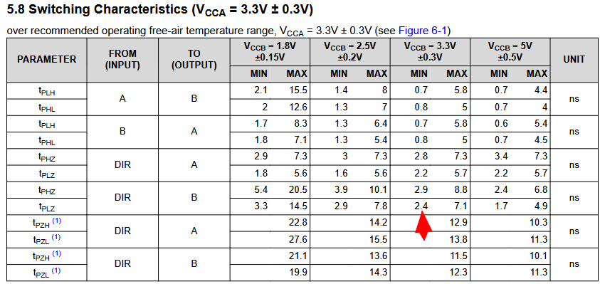
Device needs 4.75 to 5.25 volts, but the IO is 3.3volts. The buffers are CMOS so the minimum high when VOUT is 5volts is 3.5-3.7v. The Bus Pirate can’t power the device and view the high level of USB at the same time.

This is perhaps a Bus Pirate short coming. Maybe there should be a way to choose what voltage to run the IO buffers independent of the VOUT. Even two options:

  • Powered by VOUT
  • Powered by 3.3volt internal supply

So the current proposal is to add:

  • 3.3volt regulator
  • 2 additional bidirectional buffers

This adds two layer of buffers to switch, signal delay, switch noise/delays, etc. it also makes the PIO program much more complicated. You’ll probably want to use side set to control the buffer IO direction, but those pins are limited (5?) and must be consecutive.

As with PS/2 host, it might be a bit easier to use sepeerate pins for high/low and input (could be the FALA buffer on 6+).

It probably needs to straddle the boundary between the buffer direction pins and the buffer IO pins. IO6/7 would be data/clock and IO 0(/1?) would be direction. This will take some big planning, and the pin arrangements may not allow all these modes to share the same plank at all. I suggest you make something up on a perfboard or breadboard to get a feel.

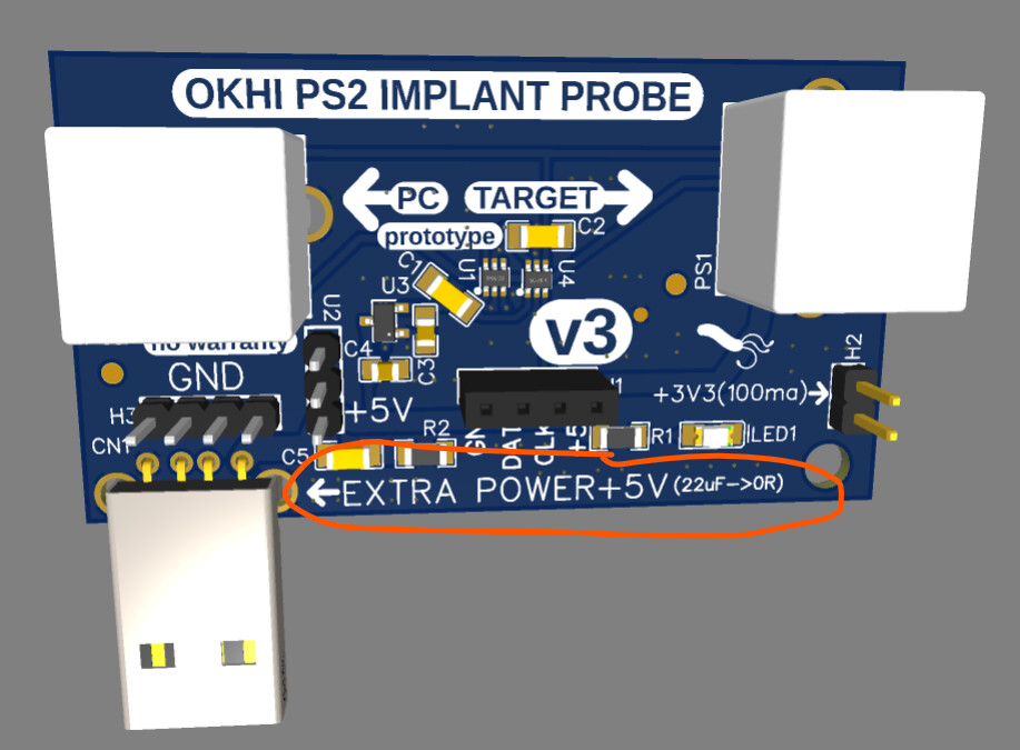
  • An easy alternative is to add a 5volt regulator and use an external supply. The supply could be via the unused USB A or C connector with a “power only cable” or power bank/USB charger. We could even add a second “power only” USB C connector with no data lines connected.

  • Alternately a small SMPS to boost 3.3v to 5volts. However it now has a clock so the board will need full FCC/CE compliance testing.

I would focus on solving the USB 5 volt supply issue (easy) compared to some double buffer madness via the PIO. I realize it doesn’t satisfy the “completeness” urge.

Other USB host & device (?)

  • Same power issues
  • Same double buffer

I really doubt with the Bus Pirate IO buffers (double for two layers) you will be able to do much more than a Full Speed host (if that).

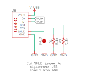
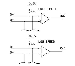
There is is also some speed indication from host (bus pirate) to device (?) using a pull-down resistor on the USB C connector pins(?). I have a whole lot of gaps in my knowledge here. For this we add a four way switch with values for:

  • Sniffing (no resistors)
  • Host mode (pulldowns to be able to detect the device’s pullups)
  • Lowspeed Device (<=12MBPS)
  • Highspeed Device (480MBPS)*

* I realize now you may mean low speed vs full speed? I am folding the info below because I’m almost certain you mean full speed after reading the thread again. Don’t LS and FS have the same pull-down value (5.1K)?

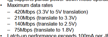
Why High speed USB probably isn't possible

The max speed even for 3.3 to 5v is less than USB High speed. We’ll be doing 3.3v to 3.3v which is about half that. Also, is the PIO really capable of operating at 480mhz or above? I guess the device may have a fall back?

Don’t forget to factor in direction switching time (perhaps x2, depending on how it is controlled).

Things I can’t match to a feature

Suggestion to add 3.3volt VREG and 1t45 buffers fixed to input to avoid pushing 5.0v accidentally into a device. I assume this is for a sniffer only board? Otherwise they have to be manipulated for the USB keyboard host.

Closing thoughts

I’d like to hear if @dreg has successfully done a PS/2 host (and then USB host) via the Bus Pirate buffered IOs.

If not, that will be a project unto itself. I suspect it will reveal the amount of sorcery needed to make this all work through double buffers, let alone in a single unified plank.

2 Likes

Oh, and @Dreg, be sure to make the io buffers output for the pins you use for communication between PIO programs. Otherwise the RP gpio and the buffer IO are in contention. The benefit is that you can logic analyze the internal signals and help debug.

1 Like

Speed Identification

@ian At the device end of the link a 1.5 kohm resistor pulls one of the lines up to a 3.3V supply derived from VBUS.

This is on D- for a low speed device, and on D+ for a full speed device.

(A high speed device will initially present itself as a full speed device with the pull-up resistor on D+.)

The host can determine the required speed by observing which line is pulled high.

https://www.usbmadesimple.co.uk/ums_3.htm

So we need a slide switch (PLANK as USB DEVICE) to connect the appropriate speed identification resistors—one position for Low-Speed, and another for Full-Speed.

High-Speed is not possible under any circumstances.

I like this idea—in fact, I do the same thing when I need extra power in keyboard implants. Check this out:

@electronic_eel If we do it this way for the USB HOST versions (leaving VOUT disconnected via the Plank’s slide switch),
do you see any problems with the scenarios we’ve planned?

Anytime we want to use USB in HOST mode in any scenario, we simply make it a requirement to connect that extra USB power only connector to a separate USB port to pull 5V + GND externally—and that’s it.

In USB HOST + PS/2 simultaneously scenario:

We can leave the PS/2 lines with (internal BP o external?) pull-ups and:

  • To send a 1, we simply leave the BIO floating
  • To send a 0, we pull the BIO to GND
    (Since sending an OUTPUT HIGH in this scenario would push out 3.3V on PS2 lines, which we want to avoid and this is a “open-collector protocol”)

On the USB side, any OUTPUT HIGH would also be 3.3V.

We can do INPUT and OUTPUT on both protocols at the same time without any issues. This way, we don’t need extra buffers—everything is simpler, just like @ian suggests.

What do you think?

2 Likes

Have you done host for PS2? That’s what I need to know.

1 Like

Not yet, but the protocol is very simple—I don’t see any problem implementing it.

We just need pull-ups on the PS/2 lines, and when the host wants to communicate, it creates an inhibited bus state by pulling the line to GND, and then everything starts.

The host can interrupt the device at any time by doing this.
(Super simplified explanation)

1 Like

FEATURES

We need to create a PCB design that enables or facilitates all of this - or at least most of the useful features.

:white_check_mark: PS2 Host/Device + USB Host/Device (both PS2 and USB protocols at same time)
:white_check_mark: Sniffing PS2 and USB (Low-Speed and Full-Speed)
:white_check_mark: Pure USB Device (Low-Speed and Full-Speed)
:white_check_mark: Pure PS2 DEVICE
:white_check_mark: USB Host (Low-Speed and Full-Speed)
:white_check_mark: PS2 Host
:white_check_mark: PS2 Keyboard → USB Keyboard (pure Plank conversion)
:white_check_mark: USB Keyboard → PS/2 Keyboard (pure Plank conversion)
:white_check_mark: Hybrid conversion scenarios via the Bus Pirate’s USB-C composite device


Proposed PCB Changes

We’re leaving out the 3.3V regulator and the two 1T45s, due to the complexity and potential issues they could cause.

Just a reminder—we have a slide switch to disconnect the Bus Pirate’s VOUT from the Plank’s power rail.

Starting from the latest design shared by @ian:

  • Connect the trigger pin pull-up to the VCC of the PS/2 and USB connectors (NOT to the VOUT of the Bus Pirate).
  • Add 10k external pull-ups to PS/2 CLK & DAT lines.
  • Add an additional slide switch to set the USB device speed (for pure Plank USB Device mode).
    • This switch simply connects the correct Full-Speed or Low-Speed resistors to the data lines depending on the selected position.
  • Add an extra USB power-only connector for USB scenarios.
    • And also, this enables bidirectional communication on the USB data lines without issues, and ensures PS/2 can be used simultaneously.
  • Implement the very low pulldown sensing approach to detect the state of the USB lines (for USB Host).

Simplifying the usage: Whenever USB is going to be used, the user just needs to plug in an extra USB cable + slide switch VOUT=off, and that’s it.

@electronic_eel @ian Do you see any issues with this design?

2 Likes

If we want to simplify the Plank even more, we could remove the VOUT slide switch and just leave VOUT disconnected. And the user won’t have to deal with when or how to use the VOUT slide switch.

That way, in documentation add a: connect the extra USB cable for power, and everything becomes easier to use (for all scenarios PS2, USB, PS2 + USB both at same time…).

What do you think is better from a user newbie perspective?

Even if it’s not strictly necessary in some scenarios, it’s about simplifying the experience for a novice.

Something in doc like: Hey, by always connecting that extra cable, everything will just work, without the user needing to worry about when it’s required and when it’s not.

Do we remove the VOUT slide switch or not? with the current design In principle, it will only be used in PS/2-exclusive scenarios.

@henrygab @electronic_eel @ian

1 Like