I added one to the schematic.
3 Likes
Outstanding! Well done on getting this up and running so quickly!
2 Likes
the trigger PIN pull/up to VOUT instead of VDD (Remember that there are scenarios where the I/O buffers are at a different voltage than the board’s VDD—for example, in USB we might have 5V for VDD and 3.3V for the I/O buffers, slide switch must be used to disconnect VOUT from VDD in this scenario)external pins to add external power supply to plank
Working out some fine details for the next revision with @dreg
1- For ALL SCENARIOS: The trigger must always stay tied to Bus Pirate’s VREF_PIN
2- For ALL USB HOST SCENARIOS WE NEED EXTERNAL SUPPLY – 5V Plank’s VCC but 3v3 IO BUFF: We should add two 2.54 mm header pins (an external Plank’s VCC + GND supply) —or an extra USB-C connector (EXTERNAL PWR): , e.g., Host → a gaming-keyboard that draws up to 500 mA.
—
Option 0 - Keep the slide switch
DANGER: 5 V may hit the D+ and D− lines and the USB sniffer could stop working (the user forgets to move the slide switch, So Bus Pirate’s VREF_PIN is connected to Plank’s VCC)
—
Option 1 – Keep the slide switch + add a low-drop diode
Add an SS14 (or similar) diode in series with Bus Pirate’s VREF_PIN → Plank’s VCC. PS2 & USB Devices should still run at ≈ 4.7 V. The user can inject a solid 5 V through the external supply pins if 4.7 Plank’s VCC isn’t enough.
- Pros • Simple, In PS2 host mode, the slide switch plus the Bus Pirate can power the target device directly (with only the diode’s voltage drop).
- Cons • drop volt for USB & PS2 devices
—
Option 2 – Remove the slide switch altogether
Disconnect Bus Pirate’s VREF_PIN from Plank’s VCC. Forever
- Pros • Safest approach—IO reference is isolated, and the sniffer always works.
- Cons • In PS2 host mode, the target must be powered via the external PSU pins (like in ALL USB HOST SCENARIOS)
—
Option 3 – Keep the slide switch + replicate the Bus Pirate cut-off circuit ← Probably the best solution.
On the plank, duplicate the Bus Pirate’s backflow protection so Bus Pirate’s VREF_PIN is disconnected from Plank’s VCC whenever Plank’s VCC > Bus Pirate’s VREF_PIN – the cut-off will always happen in all USB Host & USB Device scenarios (because IO BUFF is 3v3).
- Pros • Safe and no diode drop. Even if the user forgets the slide switch, everything keeps working. In PS2 host mode, the slide switch plus the Bus Pirate can still power the target, and the USB sniffer always works.
- Cons • Requires more work, more complexity, and more components than simply adding an SS14.
| Bus Pirate | Mode | BPIO | VOUT | VEXT | SW1 POS |
|---|---|---|---|---|---|
| PS2 | Sniff | 5.0V | – | 5.0V | EXT |
| PS2 | Host | 5.0V | 5.0V | – | VOUT |
| USB | Sniff | 3.3V | 3.3V | 5.0V | EXT |
| USB | Host | 3.3V | 3.3V | ERR! | EXT + 5V external? |
So if I understand:
- If SW1 POS is VOUT and the board is setup as a USB sniffer: IO pins at 3.3volts, USB device and host cables connected
- The IO pins go to 5volts, which is out of USB spec (3.3volts).
This is a user error we are trying to prevent?
I looked at diodes quickly, not sure there is a cheap one that won’t drop too much voltage.
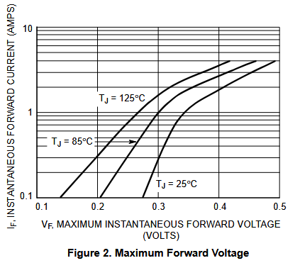
At 100mA at room temperature (lowest defined for this diode) the drop is already < 0.25volts. Would the PS2 host mode keyboard tolerate that?
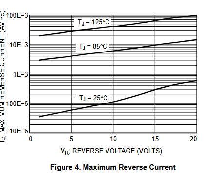
ETA: can’t forget about the awful reverse current, especially at higher temperatures. This may still result in some higher voltage on the pins than expected.
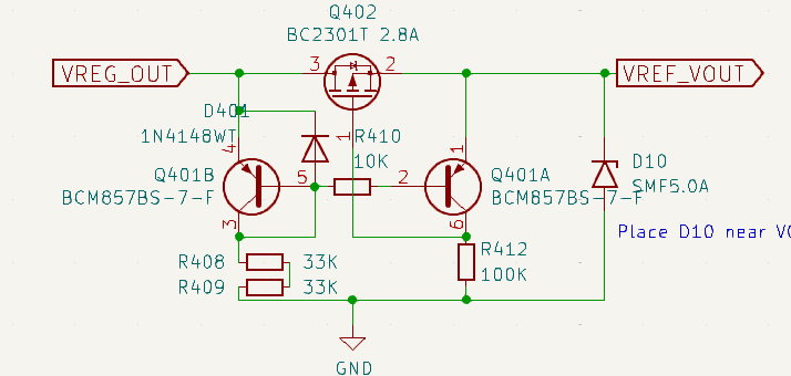
This may be the best option. The BCM857BS is expensive, but we buy them in bulk already.
Normally I’d say the user should just be aware, but if we’re pumping 5volts into a laptop 3.3v usb line - I do think that is something to be concerned about.
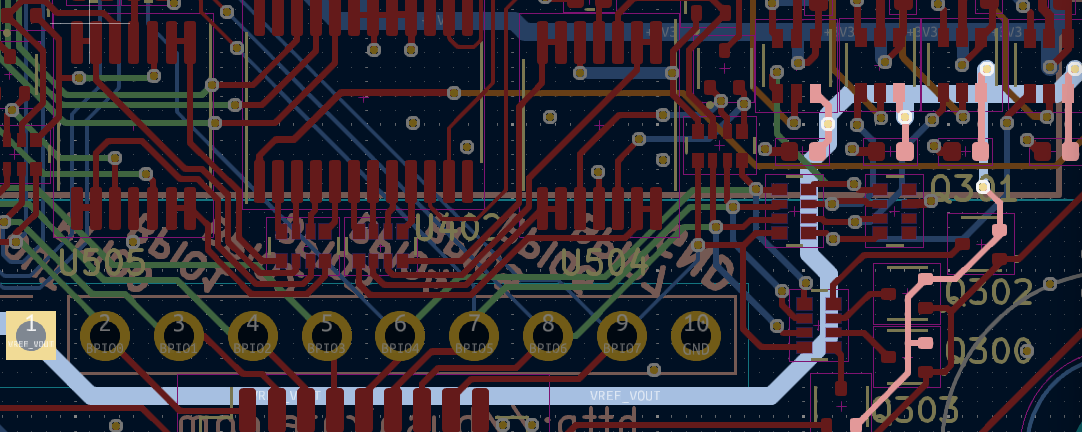
Changes for the next version:
- The TRIGGER pin must be connected with a pull-up to the VOUT pin of the Bus Pirate, and after this connection, the cut-off protection should be placed.
- Add cut-off protection by copying the implementation used in the Bus Pirate itself.
- Add 2 pins for VCC + GND to allow the use of an external power supply when needed.
- Remove slide switch.
right @ian ?
1 Like
Schematic updated. I’ll sit on it for the night and then ask Supul to route it tomorrow if there are no other changes.
1 Like
So that everyone understands the current risk with the slide switch, a simple example:
If I configure an SPI mode at 3V on the Bus Pirate and suddenly 5V enters through the VOUT pin, the I/O buffers of the Bus Pirate will immediately start operating at 5V!
Look CS changes (3–>5) when I connect +5v to VOUT:
Whatever you previously configured (3v) doesn’t matter—whatever is connected to the Bus Pirate’s VOUT pin takes control!
That means Bus Pirate’s 10k-internal pull-ups + OUTPUT pins will be at +5V, and also, smaller voltages from +3V3 devices might no longer be recognized as a logic 1 (two problems).
This is exactly what we’re trying to prevent with the proposed changes—to avoid a scenario where the user accidentally leaves the SLIDE switch in a position that connects the +5V USB SOCKET to the Bus Pirate’s VOUT, causing the BIO pins to start running at +5V, with all the risks and issues that come with that.
If the sniffer or something else doesn’t work, that’s not a big deal—but sending +5V to the D+ and D− lines of the user’s PC definitely is.
But then why did you add the slide switch? in USB Host & Device it’s useless—since the BIO buffers run at 3.3V and you can’t use VOUT 3v3 to power USB devices. In USB Device mode, the +5V comes from the user’s PC, and in USB Host mode, we’d need an external power supply.
Well, it was useful for when the plank works as a PS2 Host, and you want to power, for example, a keyboard from the Bus Pirate’s VOUT at +5V (in that protocol the I/O lines also operate at +5V).
But with the cut-off circuit, we get the best of both worlds: You’ll only need external power in the case of USB Host mode (That’s why @ian just added two pins to allow connecting an external PSU)
1 Like
Test firmware is merged into the ps2_usb_sniffer branch, and I merged it with the latest main.
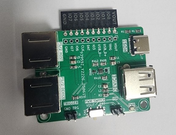
A PS2 to USB keyboard adapter should arrive in a moment, then I can start testing ![]()
2 Likes
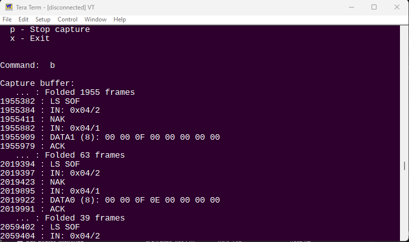
I am able to capture USB frames and see the buffer ![]() No idea what it means, I don’t know USB very well. The trigger doesn’t seem to work with my keyboard/setup, it hangs until I unplug the board. Do I need to enable some pull-up or something?
No idea what it means, I don’t know USB very well. The trigger doesn’t seem to work with my keyboard/setup, it hangs until I unplug the board. Do I need to enable some pull-up or something?
For some reason it didn’t occur that the silicon keyboard would actually type into my computer, caused much chaos ![]()
Doh! I totally forgot about the male to male cable! I’ll have one shipped with rev1 of the plank. REV1 just went for assembly.
3 Likes
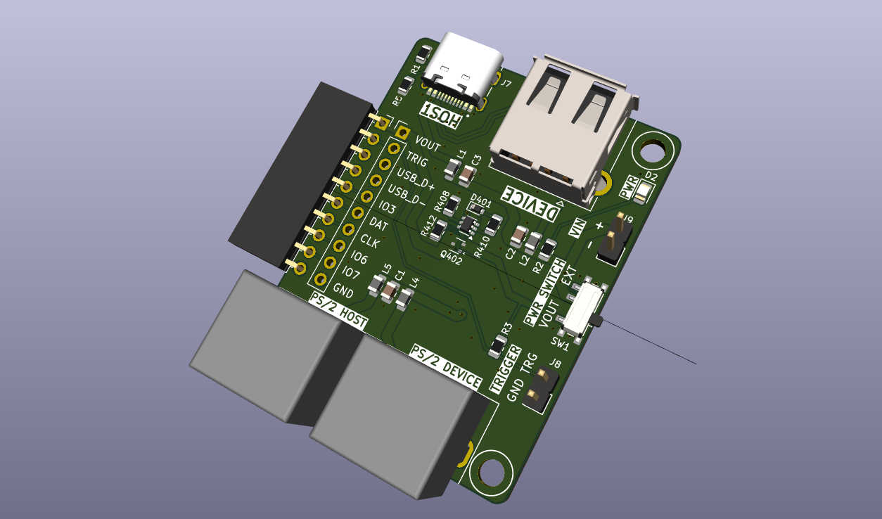
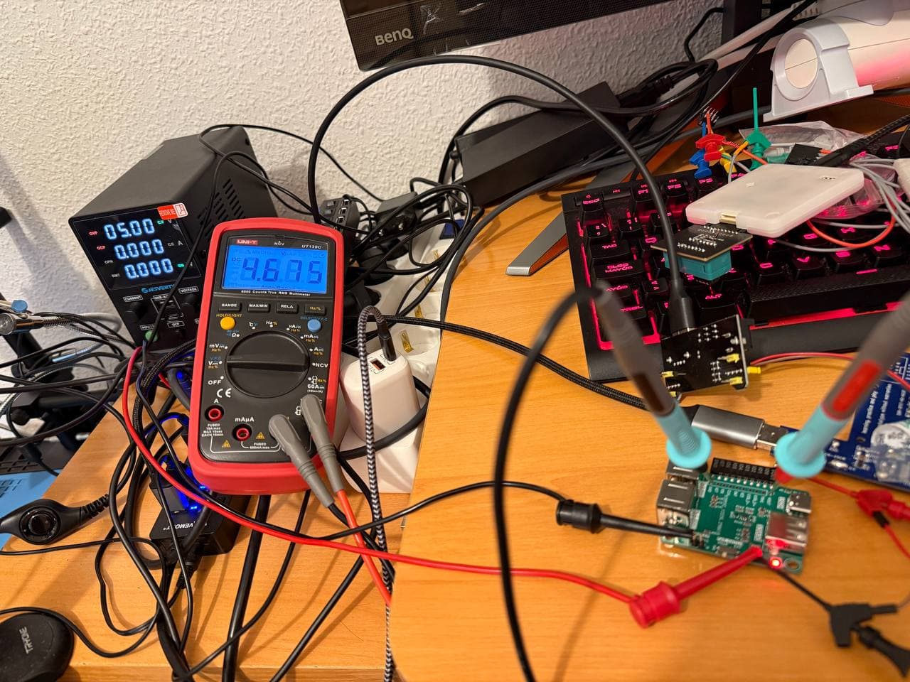
I’ve got the new plank at home now—did a quick and superficial test of the new cut-off circuit and it seems to behave as it should. The trigger is also where it needs to be. I’ll start testing and improving the firmware soon—thanks, @ian !
3 Likes
Nice! Mine hasn’t arrived yet ![]()
1 Like