Interesting, SZLCSC small volume price is better for a couple of these. The WS72324Q seems really appealing to me, mostly from a “clean” design perspective.
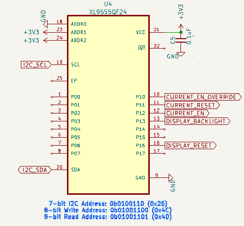
XL9555QF24 remains stubbornly expensive, but I think we can get by without it.
We also have some clarification on the TPC5120: 30kuai for samples (ordered 5), 13kuai for 100pcs+ (small first run). That seems reasonable to me, not being keen to buy a reel (3000pcs).
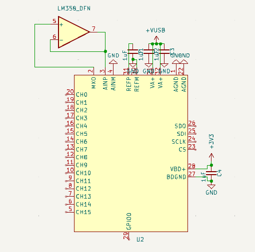
Yes, you are right, adds a bunch of passives. Even if we go to a 50:50 voltage divider and can then use one 4x resistor pack for two channels the passives would still take quite a bit of space.
Uh, nasty. I considered the glitch-thing mostly from the ADC perspective, but you are right, the glitches also affect the data lines in an unpredictable way. Open collector busses like I2C are more affected than push-pull. But this adds an issue that is hard to figure out for the end user.
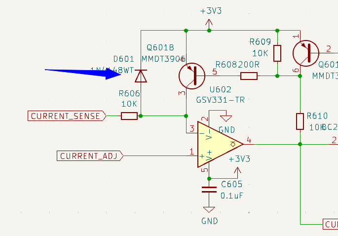
Resistor + Cap will reduce it, but you won’t get rid of it 100%. Opamps are the better solution because they isolate it fully.
A completely different idea for carving out more board space:
Have you considered using a small daughterboard and moving large components onto there? Like NOR flash and PSRAM, because they are large and just have few, shared connections.
The daughterboard could go next to the lcd on the pcb, where the button is. The daughterboard would have castellated edge connectors. It could be manufactured on the same panel as the BP and cut off after reflow. Then the castellated edge connector is hand-soldered onto the bottom side (from Kicad perspective) of the pcb, next to the lcd.
Maybe you’d need a cutout in the daughterboard for the button, so that it can stay at the same height as it is now. Having the button on the daughterboard would be nicer though because then it could be reflow-soldered.
Would something like that fit into the new case?
Would it work if the daugherboard is on a different panel and made with a thinner pcb with like 0.8mm thickness or similar?
How would adding this extra step during manufacturing with like 10 pins hand soldered work out cost-wise?
How about the firmware for 7 Rev0 then? It will be the only one with the DACs. Is developing the firmware worth the effort for just one test run?
Do I see it correctly that the XL9555QF24 is 2.2 yuan while the TCA6416ARTWR is 2.3?
Wouldn’t it then be better to just use the TCA6416ARTWR everywhere?
Or was the price for the XL9555QF24 not final yet or did I mix something up?
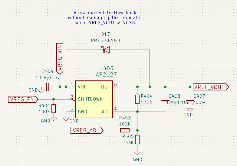
yes, this is like I planned it. In the layout it should be moved close to the VOUT pin, maybe add a comment about that.
This is a bit of a difficult decision:
the most important thing to protect is the PC
the next thing the BusPirate and it’s components
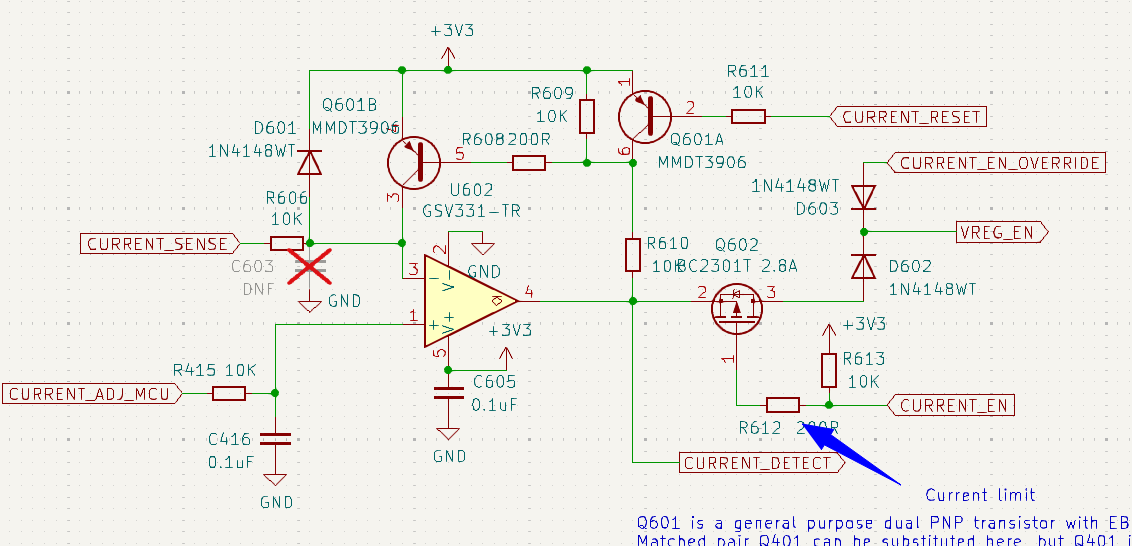
My original idea was that the VOUT-protection would disconnect any voltages that could get dangerous for the PC. So I added the diode to protect the voltage regulator.
The SMF5.0A helps, but won’t be able to protect the PC as good as the VOUT-protection. So I’d say leave out the diode, so that in case the SMF5.0A is not good enough, the voltage regulator will die, most probably short to ground and protect the PC this way.
In the original circuit you had the backflow-protection that I removed when adding the VOUT protection. After my tests with the AP2127 I’m not sure if it will be enough to protect it. Because it is an internal zener diode that will begin to conduct, not the regular circuitry of the AP2127. So I wouldn’t bother adding it back.
I suggest to wait until I have a 7 Rev0 on my desk and can measure the voltage droop on this rail. Then we can decide if we want to improve anything there or not.
I don’t mind that, it shouldn’t be much effort. I do not want to maintain that code long term if we were to swap back and forth between version though. Testing I think is fine. Or worst case: ignore that section and power everything through VREF.
At this point I just want to get some hardware to see if we like the changes we’ve made. We could keep pushing back for the next REV but I worry it could drag on for a while.
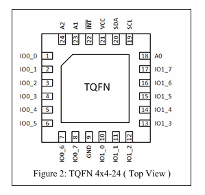
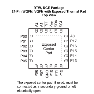
TCA6416ARTWR only has one address pin, so we can support two on a bus. The XL9555 has the same base address 0b0100 but has three address pins.
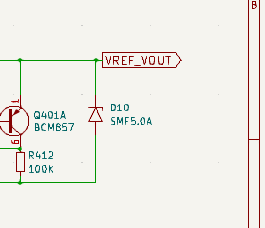
I think it works for <=5volts, but it isn’t intended to keep high voltages out. The matched PNP pair limits its use to <5volts. The purpose is to alert the user that an external voltage is present that is higher than the PSU output. It also keeps <5volts from leaking back into the analog bits, which may be of questionable value in practice.
Ah, sorry, I didn’t do a full check before writing.
So we need the XL9555QF24, or something similar that is cheaper.
My tests showed that the AP2127 will not let current flow back all by itself below some threshold, IIRC somewhere between 5.5 and 6 volts. So additional backflow-protection isn’t necessary for the region <5V.
And above the threshold internal zener diode of the AP2127 begins to conduct. So again, no current flowing back to Vusb. But the internal zener diode will at some point get overloaded and the AP2127 die.
The new SMF5.0A will help with the AP2127 surviving, but just for some combinations of voltage/current-capability.
So I’d say leave out the backflow-protection and we’ll see how well all that works out when I get a 7 Rev2 sample to fry.
Removed one more spurious part. In theory this would be a Schottky protection diode for the comparitor. I never populated it during initial prototypes. Then it went to certification with 1N4148 installed, so it remains. Yes, then it remained for two more versions 1n4148 forward voltage is too high to actually serve any protection purpose here.
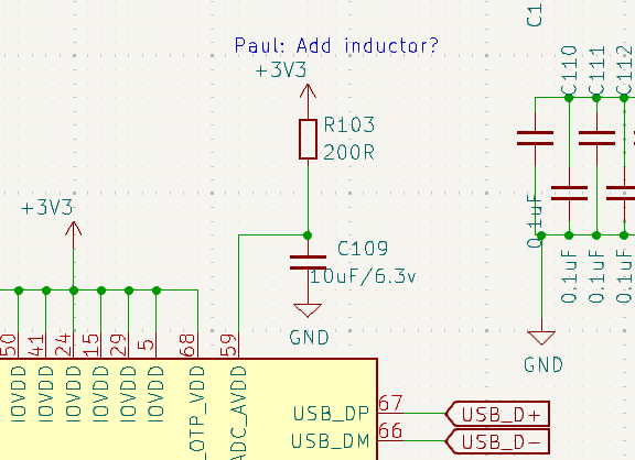
I did a few pin changes to 7REV1-PC1, and it feels like time to route the board. I’ll contact our CAD guy this afternoon.
Let’s keep detailed notes of any BP7REV2/BP8 changes from now until the board is routed. I’d like to apply them to the final board to save time routing the next revision.
I don’t have time to do that right now, but wouldn’t it make sense to see if there are cheaper alternatives to the XL9555QF24 available? Maybe even from western manufacturers that sell huge quantities.
I got the impression that this part will stay for future revisions, so investing like half an hour into this could be profitable.
This one isn’t primarily a GPIO expander, but a LED-driver. Look for the PCA9523 to get an english datasheet. It can also be programmed to be GPIO, but it doesn’t have a push-pull output, just open-drain.
It could be used in a pinch, but I’d prefer something with true push-pull drivers to be more flexible regarding it’s usage.
This one would work I’d say.
This should work too.
This is the small brother of the TCA6416ARTWR. Unfortunately it’s bus addresses clash and they just have one address pin. So it won’t work.
So which of the working ones would be cheapest at your scalpers?
Ah, thank you. I did see the emphasis on LEDs, but it didn’t look like a brand I’d want to use so didn’t dig further. The diodes Inc part seems cheaper.
Requested quotes for both candidates.
What surprised me was that this is basically it. This is the I2C QFN Io expander footprint (on the low end). I expected to find a bunch of incompatible packages, but it seems very standard until you get to expensive Microchip IO expanders.
There are NXP and TI making parts compatible with each other. One with TCA and the other with PCA prefix, P for Philips. The alternative is mostly Microchip with their own lineup that is incompatible with the TCA/PCA ones.
Then there are the older and more basic 8574 clones. These also don’t have a push-pull output.
And it seems Pericom (now Diodes) also has a few parts in their lineup, modeled after the TCA/PCA parts.
I would have expected some new players like WCH to develop their own parts for this space. They have one, the CH423, but they just seem to design for people with much board space since the package options are DIP28 and SOP28…
I don’t understand why they develop new ICs with such ancient packages. I don’t say they should just start out with WLCSP in 0.35 pitch, but is TSSOP and QFN too much to ask?
QFN seems to be too much to ask. I get the distinct impression leadless is a separate outsourced process that they don’t like.
No idea why TSSOP would be hard.
Maybe the market is replacement of existing high volume low end stuff? This would make sense for eg the CD4067. Is anyone clamoring for an 80s chip in DFN? (Besides me).
It would be interesting to visit gainsil and hgsemi to find out why this situation exists. That seems like a tea table conversation rather than a WeChat message.
It could be that the cheap bonding machines can’t do this due to some missing features. Or the extra step that cuts off the overhanging pins after overmolding requires new machines or something like that.
Yeah, I would like to have such a conversation with them. But you’d need the right people on the other end of the table - that not just look in their spreadsheet and tell you the options, but that also know why exactly they decided to not offer these packages.
While raw PCB space isn’t really expensive for their Chinese customers, end product size still is. You need a case around the pcb, shipping costs matter and end customers don’t like bulky stuff.
So I guess they also have demand for smaller packages.