Just wanted to highlight this project stumbled onto over on YouTube. I haven’t looked any deeper than just watching the video in the background while working on a MicroPython project. But there could be some useful information there for cross pollination of projects.
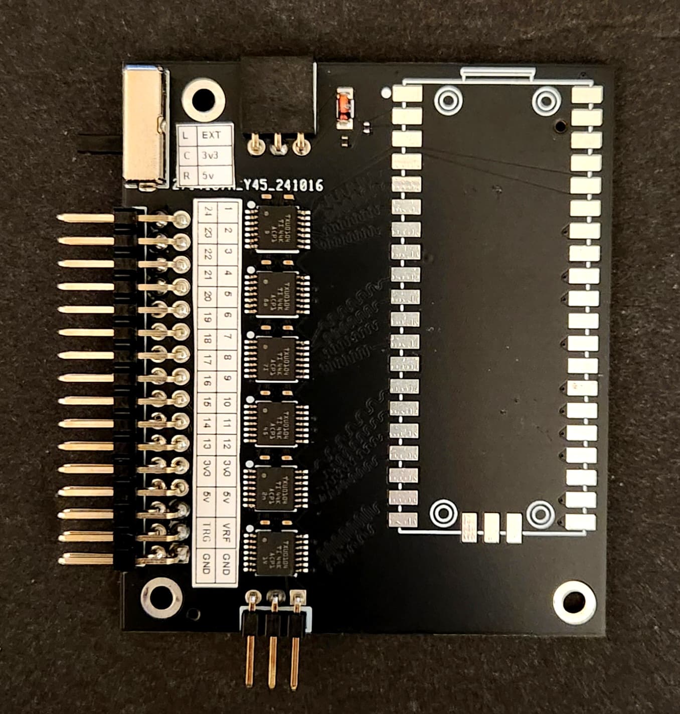
FYI, the populated boards (which disappear fast - as they are first come-first serve), are about 50€ (25€ + delivery from Spain to the US) - and that doesn’t include the RPi2350. You have to sign up for a waiting list. I haven’t had a chance to play with it yet. Apparently it can sample up to 400Msps in a limited burst mode. Contact logicanalyzerorders@gmail.com if interested.
If anyone can help out, I am looking for the latest Raspberry Pi Pico2 model or datasheet? I’m on the go and the only one I found was not the most current.
The beta software changes frequently, but he hasn’t updated the public source. This link is dated Dec 14th. but it only includes the binaries for the firmware and the logic analyzer.
-Pico2 now is supported.
-Added Sigrok protocol decoders to the software.
-New terminal capture application.
-Many enhancements to software/firmware.
-All in one packages.
-Included gerber files and BOM/Centroid.
-Too many changes to specify here, please read the Wiki once updated. Release Release 6.0 · gusmanb/logicanalyzer · GitHub
OK, I now have need of the logic analyzer functionality. I’d like to learn how to use gusmanb’s software with the BP6 hardware, primarily because he now supports the sigrok protocol decoders (and I’ve had trouble getting sigrok working in the past).
Is the LA binmode (as usable by GusmanB’s LA) a stable feature now?
If so, is there an existing write-up / tutorial?
Note that I’ve have not previously installed gusmanb’s software, nor used the BP6 LA binmode before … so installation gotchas also appreciated.
There is no compatible binmode yet, but all the infrastructure is there to support gusmanb. There may be updates for RP2350, which was an improved DMA which may make things easier.
There is also a port of the original gusmanB firmware.
I had an issue with the client, but it was quickly resolved in the issues on github.
If I understand correctly, I could load the ported firmware on the BP6, and it will work with gusmanB’s LA software? If so, where do I find that alternate (port) for the BP6?
Hi Ian,
Sorry for the newbie question, but looking at the gusman pcb design, it seems not much more than a pico2, so I was wondering what would a port to the Bp6 require?
I know I can just get the gusman design PCB made up and solder on a pico2 I have lying around, but since I have a nice shiny BP6 I’d love to use it for this.
The GusmanB logic analyzer is pretty easy to port (or was when I ported to BP5). There are the basic steps:
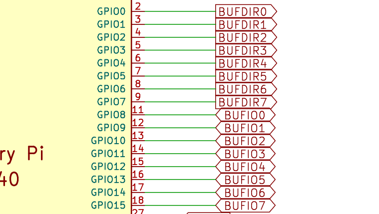
(Optional) We have buffers, set to input by default, so nothing really needs to happen here. For good measure, make the buffer direction control pins (GPIO0-GPIO7) outputs and to ground during initialization. This will ensure the buffers are firmly held as input to the RP2350.
Our first IO pin is GPIO8, I believe GusmanB uses GPIO0 as the first pin. We have 8 pins and GusmanB has a bunch more. The PIO program needs to be modified to use 8 as the starting IO, with 8 pins total. I forget exactly how to do this, but part is literally changing pin 0 to pin 8 when loading the PIO program.I believe there is already an option in the source for 8 channels only.
Disable any indicator LEDs. They might trigger hardware connected to the Bus Pirate, depending on the pin used.
(Optional) Enable a power supply. The buffers need to be powered. This can be done with an external supply on the VOUT pin (easy), or using the on board power supply (harder). There is a library called pirate-lib that drops into a project and gives basic control of the Bus Pirate hardware, from here you can enable the PSU.
Basically you copy the pirate-lib folder into the source, then create a pirate_config.h to contain any initialization code. This example loads the display and enables the PSU if the button is pressed.
Finally, include pirate.h and any additional features somewhere early in the initialization function and call pirate_init();.
Here’s one tricky part - pirate-lib only supports RP2040 based Bus Pirates at the moment. The hardware defines are here in pirate.h, they need to be replaced with the contents of the BP6 platform file. Ideally it should be merged so both RP2350 and RP2040 chips are supported, but that is excess work
I created a fork of the GusmanB logic analyzer for a Bus Pirate port. I am unable to take on this project at the moment, but I will make time to support/contribute to port if you (or anyone) helps it along. Of course I am here to help with any roadblocks as well.