Here’s the next step in glitching - power glitching.
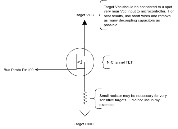
I used the blank plank proto board to put together a really dumb simple circuit: BP IO00 goes to the gate of an N-Channel FET. The device’s Vcc/Gnd go across the source and drain:
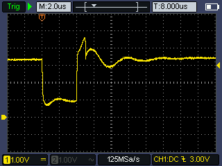
The voltage across the FET when a glitch pulse is triggered:
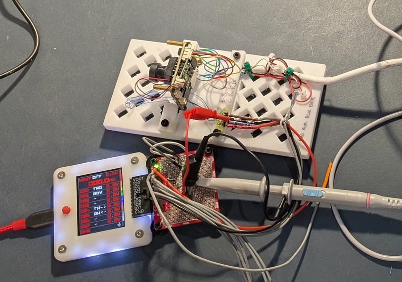
The blank plank has pin headers for making the device connections with a couple of extras for hooking up a scope, for example:
In the case of my target, U-Boot is prompting for a password. You get as many tries as you want (bad security), and there is no delay enforced between attempts (more bad security). I know from using a logic analyzer and reverse engineering that part of the code in Ghidra that there is about an 8 microsecond delay between entering the password and U-Boot prompting for the password again (if the password was not accepted).
Triggering a power glitch during that time may result in the microcontroller glitching/skipping over the password verification, which should allow us in without entering the password.
I have been working on a glitch command that works with the UART mode:
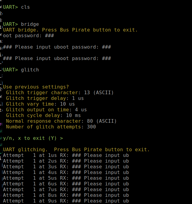
The glitch command takes 7 parameters:
- Character than triggers the timing. Here it is ASCII 13, a carriage return
- Initial delay from end of that char transmission to output “ON”
- Variation time - the code will try a pulse at the
delaytime, delay time + 1us, delay + 2us, etc. up to this variation time - output on time - how long output should be on in microseconds
- cycle delay - a little bit of time between attempts so things don’t overheat
- normal response character - something in the response from the DUT to know the glitch didn’t work; basically something in the response that is “normal” for a bad password. In this case, a capital
Pfrom “Please input …” Note - the code only reads up to 20 characters in response from DUT - Finally, how many tries to take.
It’ll run until the device returns something that doesn’t contain the “normal response character” (meaning it glitched), the BP button was pressed, or an exception happened.
The code uses a PIO program to watch the TX line to know when to start the cycle (delay, on, off).
The code is at my fork of the project, I rebase off of the Official project fairly often, so it should be mostly up to date. The code is in the files glitch.h, glitch.c, and glitch.pio in the ./src/commands/uart directory: GitHub - mbrugman67/BusPirate5-firmware at uart-glitching
This same code works equally well for triggering an external device: Any tutorial about glitching - #40 by mbrugman; you just need to set the pulse time long enough to fire the device.