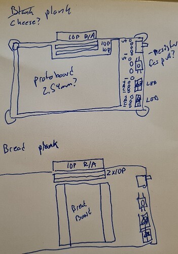
Another collector quality artwork ![]()
More like the first one. That’s even more stuff than I imagined, but I like that concept
Cool, will definitely work up a concept with a protoboard.
I like these cute breadboards, but they do lack a power and ground rail.

There are tiny and appear to be Lego compatible?
Fun fact: breadboard is literally 面包板 (mian bao ban/bread loaf board). PCBs are 电路板 (electric street board). I guessed and it turned out to be right ![]()
I like the idea of a protoplank.
Are breadboards still a thing?
I never liked them:
- Nearly all interesting components today are SMD and getting SMD parts into a breadboard always requires adapter boards
- The connections are often unstable. Maybe my breadboards were too cheap or worn out or whatnot, but I wasted hours and hours because I couldn’t figure out why my circuit was behaving strange. Always was a jumper wire just sometimes making a connection.
- Strong parasitics everywhere, wires radiating EMI, long loops: a lot of stuff I’d consider “regular CMOS” does not behave well with this
I switched to soldered protoboards and never looked back.
I even designed my own protoboard-layout some years ago:
Maybe use my design with the ground plane option? This is the one I end up using most because having ground available easily on each hole is convenient. Also having a proper ground plane improves EMI and makes even sensitive analog stuff workable on a protoboard.
I should probably update the footprint to modern Kicad some time. It was designed at a time when you needed some bad hacks to be able to create a footprint like that.
I envision this more like a combination of dirtypcbs and BusPirate: you get a 10-pack of protoboards with the fixed design and a bag of 10p connectors. Since you are already soldering, soldering the 10p connector by hand takes less than a minute extra and saves quite some production costs.
Two rows of the 10p header make most sense to me.
Not sure if fixed accessories aren’t more getting in the way than helping. The BP already comes with enough LEDs.
Nice! Sjaak who did a lot to get the original bus pirate 3.x going did a lot of that kind of board for a while.
Love the easy ground plane option.
Matt at Blinkinlabs did a talk on parametirc board design using python in KiCAD. He was super enthusiastic about it for a while. That might be a way to go and I can hit him up for tips ![]()
so i went onto newae’s website and they used to have kits for the picoemp which is the entry level to chipshouter. then i research some of colin’s video’s and how they did the timing of those attacks, hence why they put a timer on boards they created that allow sophisticated timing measures but for doing something with usb, one could get by with the greatfet glitch library, a yepkit (programmable power user usb hub or buy a adafruit usb breakout board), and then the picoemp and you may have something that resembles a toolkit to learn.
the bom list for the picoemp is available on digikey with two things i bought off of mouser. i ordered three pcb’s from oshpark (sorry ian - i had a coupon)so if anyone wants the other two, i would be happy to send them no problem at all.
I’m still thinking about this topic… I’m in the process of writing a presentation about hardware hacking for a conference next spring. I was thinking of using a Chip Whisperer for some power glitching, but I’m thinking of maybe using the BP for that instead. (I’m already using the BP in my presentation for some other stuff).
I’m hacking an embedded Linux device. The glitch comes in during the u-boot bootloader operation. I have already extracted the u-boot, Ghidra reverse-engineered it, and have isolated the code I want to glitch. There’s a routine to allow a password to get to the u-boot console. (From there, we own the device, mwuhahahaha! ![]() )
)
Anyway, this might be a good use for the proto board - I could make a circuit to do the power crowbar to induce the glitch. The BP would do the serial comms and triggering of the glitch.
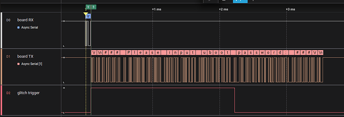
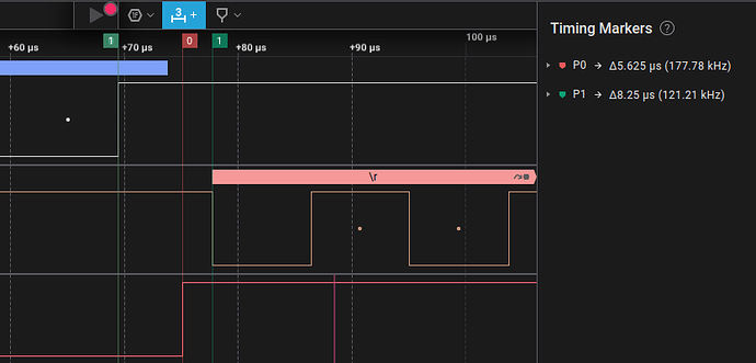
In this timing diagram, the password is entered with a newline (first channel). If the password is bad, the loop jumps back about 7.9 uS later (second channel shows a prompt to try again).
It would be a fun firmware write addition to add maybe a timing function to the UART function. Maybe even add functionality to measure TX/RX timing to find where to glitch, and then to do it.
@ian - does it seem reasonable to try to target timing down to the 0.1 uS level this way? What do you think?
Maybe the glitch could be triggered by the FALA?
So you pre-load some configuration into a special FALA-mode that looks like this: look for 3 rising edges on TX, wait n cycles and then switch a gpio line to high for m cycles to trigger the glitch. This keeps running in the background on another PIO. Then you issue the command to send the serial data which in turn triggers the correctly timed glitch.
But make sure beforehand that the BP is good enough frequency wise: Faultier overclocks the RP2040 to 250 MHz, which is double the officially supported speed. I haven’t directly seen if this runs from flash or ram. All the peripherals of the BP, like flash, display and so on would have to be checked or their clock config adapted if you want to do this with the official BP firmware.
From what I have heard the RP2350 as used in the BP6 can’t be overclocked as far as the RP2040 could. So this will probably only work with the BP5.
I’m not sure how much work the firmware side of this will be. Maybe port the faultier firmware to the BP hardware instead?
That would be 10MHz? So you have about 12 clock ticks to respond.
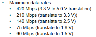
Another limiting factor is the IO buffer, but it appears fast enough?
Haha, had the decimal in the wrong place doing mental math ![]() babysitting the grandkids all week and I’m behind on sleep.
babysitting the grandkids all week and I’m behind on sleep.
There is a new topic for the Blank Plank with a very rough sketch of the PCB.
I’m in the same camp. The wires come loose, and if time elapsed, you have to get your mind back to the project. That’s one reason I ordered a Jumperless.
I’m not a KiCad guy (yet), but another prototyping option is an idea of cybergibbons. It uses stripboard, and Dupont headers - which I find to be much more resilient. You attach one end to your device under test (he uses it for reverse engineering), and then attaches various equipment (debuggers, scopes, logic analyzers, programmers, etc,) to the headers soldered onto the stripboard. You can have screw or quick connectors on one end for the DUT. He also suggests cutting through the copper on a section of the stripboard, and using female jumpers to optionally reconnect the two parts of the run. (right side of top board).
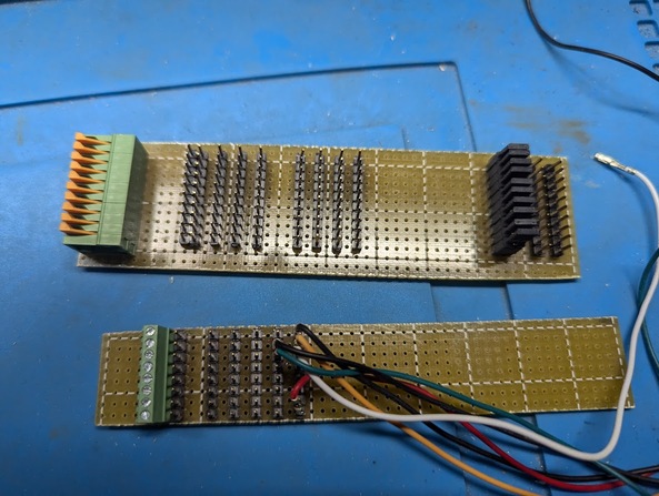
And you can add male or female headers spaced the way you like them. This is only good for connecting devices, of course. But it is handy
I’m also in the “no more breadboard” camp. I do something similar to cybergibbon’s idea, but I use wirewrap on the “back” side to manage the interconnections.
Here’s some more resources on fault injection
And this example SimpleLink-FI/notebooks/5_ChipSHOUTER-PicoEMP.ipynb at main · KULeuven-COSIC/SimpleLink-FI · GitHub
Wow! ch446q is a heck of a chip. Will keep that in mind in the future.
Another hardware resource for those who might want something midrange price based off the picoEMP. I picked one up but haven’t had a chance to use it yet, so I can’t really say how good it is. (The main problem with a lot of hardware hacking tools is unless they have a good community you are left to brute force how it works )
One thing to consider is the shipping of the Faulty Cat. It’s $50 to me (Mexico->US) added to the $115 cost makes it $165 (plus tax)
Many of the tools I own do have a community, usually discord. Ask if you are not sure.
Their shipping is flat out highway robbery.
There are a lot of books on sale today (in the US). I’m getting Travis Goodspeed’s book that has a lot of glitching tutorials. There is one homebrew board in the sample. I’m not sure if there are more.
(sorry, this may be a long post ![]() )
)
I’ve been working on a presentation for a hacking conference. I was going to talk about glitching/fault injection attacks, but not demo one. After reading this thread I decided it would be fun to do that!
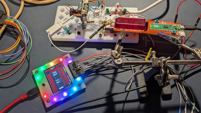
First, a few photos of the setup:
The PCB under test is mounted in a 3D printed base. The Bus Pirate is connected to the UART pins of the PCB and to a ChipShouter PicoEMP
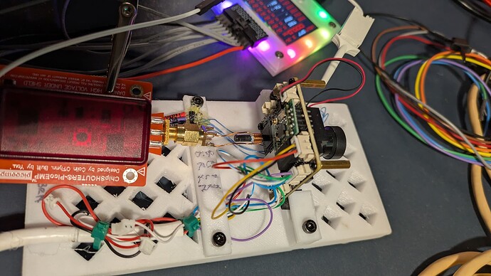
A close-up of the business end of the EMP tool up against the microcontroller
Next, here’s a quick tutorial/explanation of what I’m doing:
Background
The device being “hacked” is the PCB from a cheap webcam. In this case, we’ve found the UART pins and have connected the Bus Pirate to them and interrupted the bootloader (U-Boot).
U-Boot is prompting for a password we don’t know, so we’ll try sending a carriage return (\r) character and then firing an EMP blaster at the microcontroller during the “check” of the password.
If the password was not correct, U-Boot will send the text ### Please input uboot password ### back over the serial line. The glitch code will parse the response looking for a specified letter. If that letter is not present, then the password check was bypassed.
Code
First, I added a new command in the UART mode: glitch. You can see the code here in my fork of the main repo.
The code uses two of the IO points:
I00 - this is the output to the glitching hardware/device
I01 - an input to let the code know the hardware is ready
The basic code flow (once configured):
- Check to make sure hardware is ready (with timeout)
- Send a carriage return
- After user-specified delay, fire the output to the glitcher tool
- Start receiving from the device under test (DUT)
- Get up to 19 characters or timeout
- Parse response, looking for a certain letter (In this case, a capital ‘P’)
- If that char was not found, end
- Wait a short delay
- Count attempts, if not at limit, jump back and try again
At any time, pressing the BP button will stop the process.
Determining timing
I used a logic analyzer. I wanted to use the FALA, but I couldn’t get the libraries to load for it under Linux.
Here’s a capture of the full sequence:
The top input is the BP sending the return to the DUT
The second input is the response from the DUT to the BP
The third input shows the output
I00 from the BP
Zoomed in a bit with some timing markers:
The first input shows the end of the TX from the BP
Second input shows the DUT starting to send the “bad password” response
Third input shows where the glitch device was triggered.
Timing pair one shows the BP output went high 5.625us from the end of the BP TX. The second just shows that there’s a time of 8.25us from the send of the BP to the DUT telling us the password was bad
This was an iterative process - I changed the glitch config a few times to get the timing where the PicoEMP was firing about where I guessed the U-Boot code was checking the password.
Operation
First, I used the bridge command of the UART command to get the DUT into a condition where it was accepting password attempts. I pressed the button on the BP to stop the bridge, but not exit UART mode.
Next, issue the the glitch command. This is from the serial terminal:
UART> glitch


Use previous settings?
 Glitch trigger character: 13 (ASCII)
 Glitch trigger delay: 83 us
 Glitch cycle delay: 50 ms
 Normal response character: 80 ASCII
 Number of glitch attempts: 10

y/n, x to exit (Y) >

Hardware setup!

UART Glitcher.  Press Bus Pirate button to exit.
Attemp 1 RX: ### Please input ub
Attemp 2 RX: ### Please input ub
Attemp 3 RX: ### Please input ub
Attemp 4 RX: ### Please input ub
Attemp 5 RX: ### Please input ub
Attemp 6 RX: ### Please input ub
Attemp 7 RX: ### Please input ub
Attemp 8 RX: ### Please input ub
Attemp 9 RX: ### Please input ub
Attemp 10 RX: ### Please input ub
Target glitch count exceeded, no glitch :/

UART>
As for the settings:
trigger character was going to be configurable, but I figured most times it will trigger on hitting return, so it’s actually hardcoded right now.
triger delay is a time in microseconds from when the character is sent to the BP UART until the I00 output goes on. It’s 83 us here - the time begins shortly after the character is sent, not when the send is done. It took some trial and error with the logic analyzer to get that time
cycle delay is just a time between attempts
normal response character is a character that you’d expect to see if the password code on the DUT ran. In this case, it’s ASCII 80 for a capital P. The DUT responds with ### Pleas… The assumption is that if we don’t see that, we glitched past the check code
attempts how many times to try before giving up.
That’s the basics. I’ve gotten to the point where everything works, but haven’t successfully glitched it yet. I just wanted to share what I’ve been doing.
Next, I need to modify the firmware of the PicoEMP. If you connect to the serial port, you can arm a “Fast Trigger” mode. In that mode, there’s a PIO running (yes, it’s 2040 based); that PIO watches an input and quick-fires the EMP pulse. But you need to arm that mode each time. I will modify the firmware to just start up in that mode and stay there.
Let me know if anyone has any questions or comments. I’ll follow up if I get it to bypass the password entry.
