When I tested the AP33772S I ran into an issue where the chip expectes to be powered from the USB source, not independently as we do with the Bus Pirate. The causes the chip to hang after USB C is attached and removed once, a power cycle is needed to get it back online. This isn’t great for a design where we want the chip to be an always-on device for testing USB supplies.
The datasheet mentions that the V5V 5 volt LDO output can be used to power the chip when USB isn’t attached. It doesn’t say anything else though, such as does the external supply need to be removed to avoid damage to the on-chip LDO regulator? I wrote Diodes INC to ask, but I rarely hear anything back from chip companies.
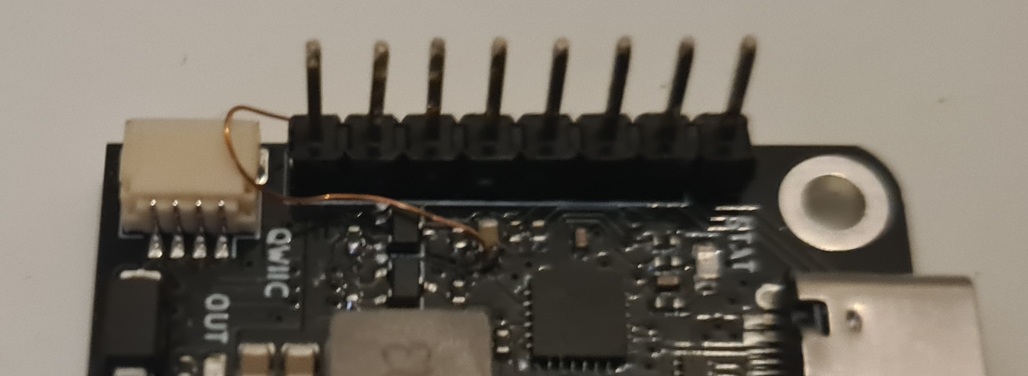
This is a bodge wire from the V5V capacitor to the 3.3V in pin of the breakout board. The 3.3v in pin is safe for 3.3-5volts, so we can feed it in there.
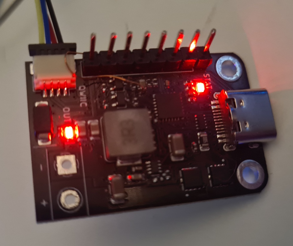
It didn’t blow up, but it also doesn’t recognize when the cable is detached.
After some extended use, powering externally doesn’t seem to instantly degrade the chip. However, I am unable to send the USB PD hard reset request. It just doesn’t do anything.
It’s going to take some thought to figure out if and how this chip is useful for a plank.
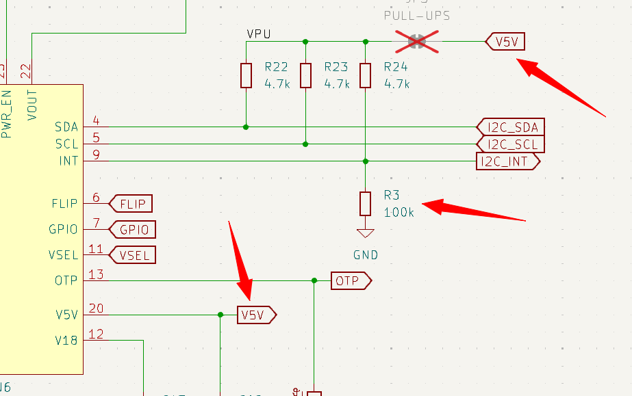
Change pull-up power from Bus Pirate VOUT to the AP33772 internal 5volt regulator. Now the chip will properly power cycle when USB supply is inserted or removed
Add 100K pull-down to the I2C interrupt pin
The Bus Pirate can sit and wait for the I2C_INT pin to go high, accessing the chip only after a USB supply is attached.
I’ll make these changes to the board and we’ll scrap the previous version.
Actually I think it was something else. I had to move all the print functions to the local file or they just didn’t get run. Not sure what is going on, but I wanted to customize them anyways so it makes sense to have a local copy.
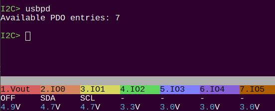
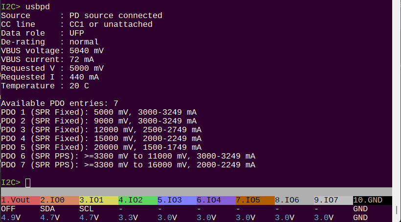
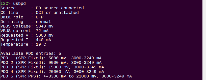
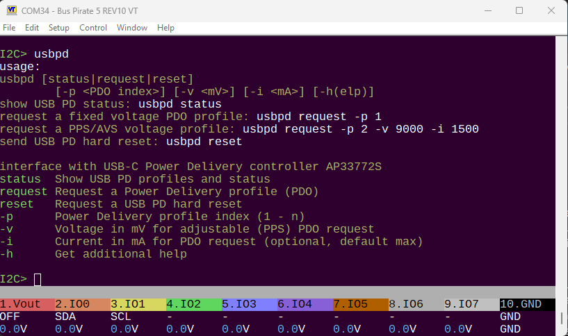
Now we’re getting the basic status info, and the list of profiles.
This seems to be the explination. The voltage leaking through the pull-ups is coming out on VOUT and raises the voltage above 0.8V and then the USB source will not deliver power. The solution is a hefty resistor between VOUT and ground, which is not a really great solution at 20+ volts.
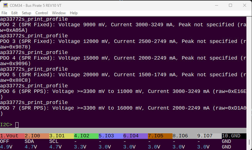
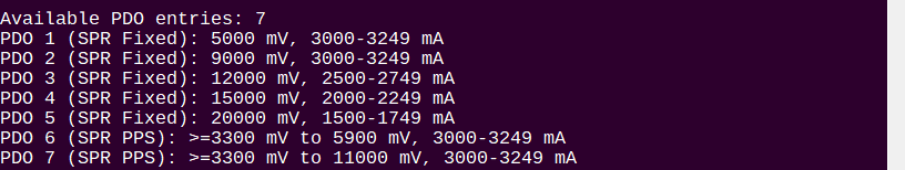
Fixed the bug where Requested Current (I) was giving the wrong values. The driver I used was treating requested V and I as 8 bit registers, when in fact they are 16 bit registers. Fixed this and made a pull request to the upstream project.
It’s looking nice. Now I just have to write the help text.
This would let you do fuzz testing of PD sources and sinks, which would be interesting.
If you had a dummy load connector and a voltage measurement facility in the plank, I think there are lots of interesting possibilities.
I’ll keep looking for a reference design for a CC phys transceiver - “DC coupled … nominal voltage… “ is not quite enough info for me to grok the electrical interface needed