Sorry for the terrible photo…
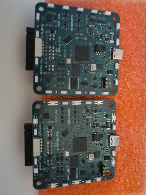
BP7 REV2 arrived a few days ago and has been sitting in the neighbors’ stairwell. Updates from previous REV1:
- VOUT protection added (to be stress tested)
- All LEDs are now 3 or 5ma version (5 as I recall?)
- One version with all side LEDs
This is going to sit for a while. I need to finish annual admin and then document the flatbuffer interface before I can even think about getting these guys going.
If what I was thinking about, the pixels would be SK6805 (e.g., SK 6805 SIDE-G), where the final two numbers indicate the mA (e.g., expecting ~40% of maximum draw vs. SK6812).
I totally missed the posts about BusPirate 7 being in development, whats the planned key feature differences vs the 5/6?
I think I will be happy with my BP6 but curious what the next version will have ![]()
more port protection aka less ways to zap it by accident.
Yeah, basically I designed the 6 in secret as part of the RPi beta program. After launch there were a bunch of great suggestions for stuff like over voltage protection so we rolled them into prototype.
In terms of features there’s not much difference. The over voltage protection is nice, but there also isn’t exactly an epidemic of failures from zapped pins.
Port protection sounds like a wish come true, I am not an electrical engineer but always wished other products had protection on ports to avoid those silly mistakes from a stray jumper or just wrong pin in general
I assume the extra components would likely increase the cost from the BP6? or you intend to replace the BP6 with BP7 once released
The goal is to have an intro model (5), a regular model (6) and a MAX model (7). 5 uses almost all generic components. 6 uses a couple expensive name brand chips, and 7 uses a whole bunch of expensive name brand chips.
The 5ma LEDs on the 7 for example are 3x more expensive as the common 12ma type. It’s just a matter of increased complexity and component expense.
I’m in for a 7! Need? No. Want? Yes!
3x more, WOW!
I know the cost of addressable pixels can be significant; so hearing that they’re 4x the cost … that’s quite shocking, and probably not worth the finer color gradients they can put out. (of course, I still am cheering for side-emitters. ![]() )
)
Let me know if you have a branch that you’d like a PR to, and I can quickly change the code for BP7R2 to:
- Read some configuration bit in OTP to determine LED direction (all-side or classic) and power (classic SK6812 or lower-power SK6805).
- Default for unprogrammed will be to use classic settings.
- low-power SK6805 will have code adjusted so that LEDs are not artifically reduced to maximum 30% brightness.
Thanks Henry!
I need a few days before I switch to this project. Getting close though.
The flatbuffers interface is “complete” for the moment. I will start bringing this up next.
So exciting!! I’d be happy to help beta test if needed! ![]()
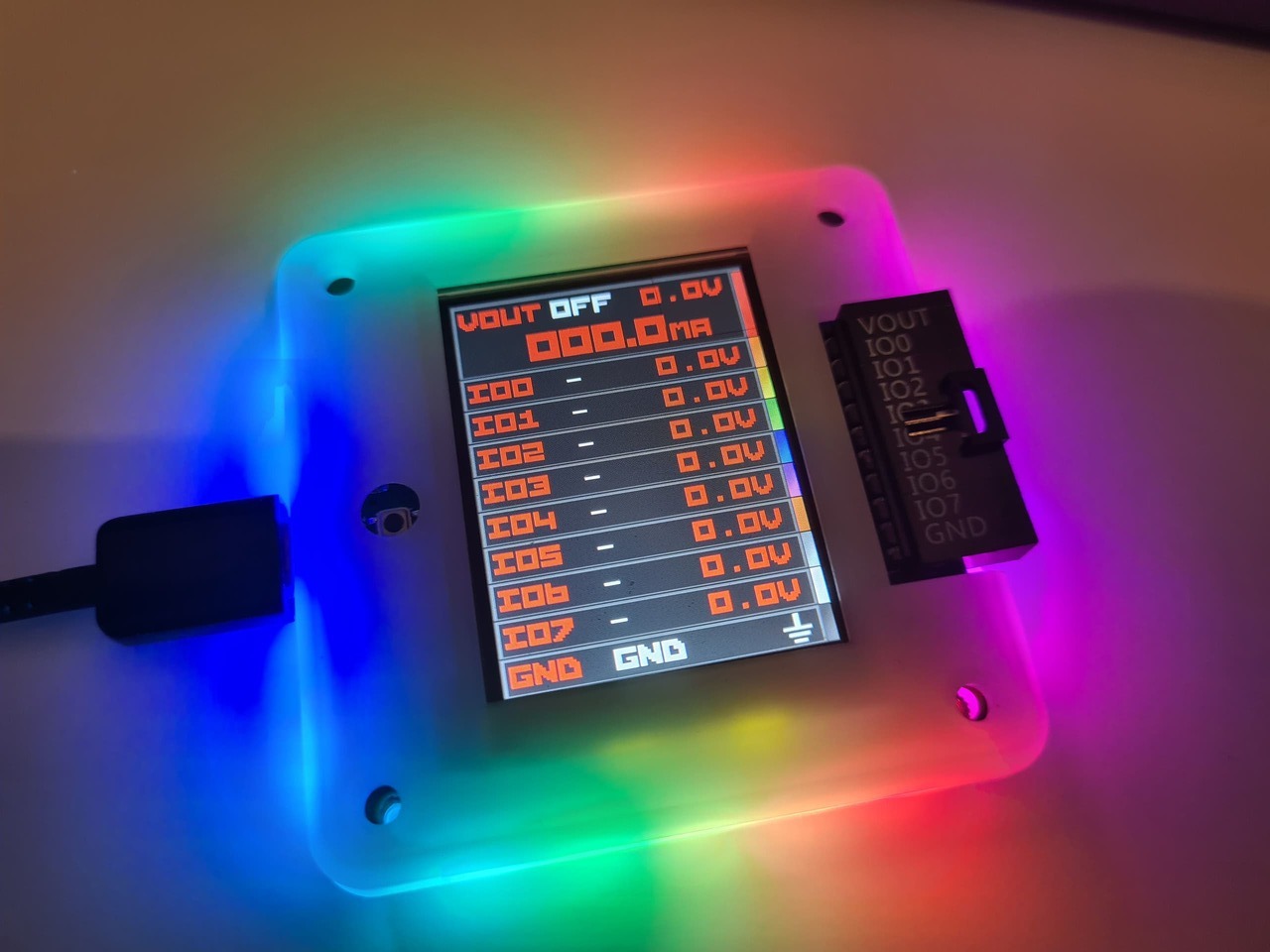
This is the all side LED version.
First bug: the LEDs under the 10P are in the way of the AUX connector tabs in the bottom of the case.
Even at 10% brightness the LEDs do a nice job of illuminating the top part of the case.
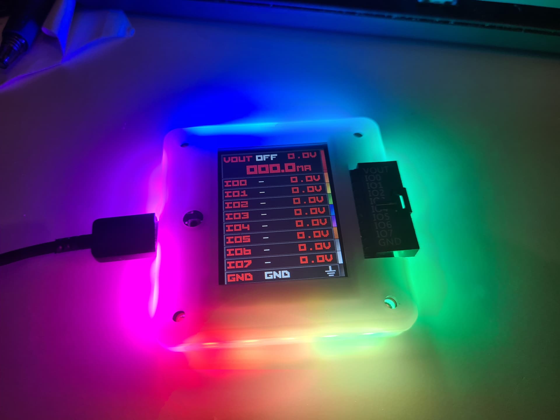
Since we have those 5mA pixels instead of 12mA, I removed the brightness divider. Still way too bright, but the animation has more steps so it looks butter smooth.
We’ll need to run a quick revision with proper LED spacing to see it fully in the case, but I do like this a LOT more than I expected too, thanks @henrygab!
Pushed a new bp7rev2 branch to git. It has minimal updates to get the firmware running, there is still much to adjust for the changes since REV1.
Whew! I’m relieved and thrilled that you like the results.
Next, can I convince you the beauty is worth updating the BP5 / BP6 layouts to use all-side-firing pixels (even if not moving to the more expensive 5ma version)? ![]()
- Henry
P.S. - Bonus: Would remove one more part from the BOM for each unit. Although if BP7 uses 5ma, net zero change in how many parts in inventory…
That’s a good question and I wrestle with it myself. At the moment I have adopted a philosophy of only moving forward. Each design is a painting and when it’s in the wild there’s no further work unless it’s defective.
Aside from the support complexity, there’s CE and FCC testing. It’s not too expensive, but it has to be added to the cost of goods sold and deducted over an expected product lifespan. Maybe there’s an argument it could be depreciated over a schedule of years, but… It increases the complexity of the accounting and we’re already at the edge of what we can manage books wise.
In a frictionless world I’d roll new updates into each batch for sure.
Updates pushed for the PSU and VOUT protection.
I have not stress tested @electronic_eel 's VOUT protection yet, but here are some observations on the two PCBs I have:
- VOUT protection does turn off and on (success!)
- There is something going on where the VOUT protection is interacting with the current measurement
– When shorting VOUT to GROUND the current sense only shows ~30ma (about 1/10th actual value). I verified it by measuring CURRENT_SENSE on the PCB, it is about .3 volts and should be closer to 3 volts.
– When shorting VOUT to GROUND through the current measurement of a multimeter, the current sense is correct - When powering the BP7R2 from the VOUT of a 5 the current draw is pretty heavy and oscillates widely. 20-50mA is used just by the front end chips, which should be 2-3mA
- Just in general the current sense isn’t as reliable as BP6, this may be due to changes in board layout.
My next steps will be:
- Stress test VOUT protection to see if it is working
- Verify and qualify the current sense issue
Verify and qualify the current consumption issue when connected to an external supply
I suspect current is leaking back through the inactive voltage regulator. It if were anything else the current draw would be similar when self powered. I’ll test this by removing the VREG and then power externally. If this is the issue, then we need to bring back the one-way switch in front of the VREG.
ETA:
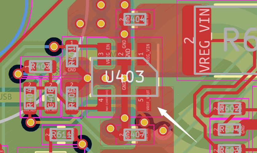
Broke the lead of the VREG trying to bend it out, but this is indeed the cause of this issue.
There is a lot of current leaking back into the inactive VREG. When the VREG is removed from the circuit the current consumption is negligible.
Seems like we need to bring back the one-way valve.
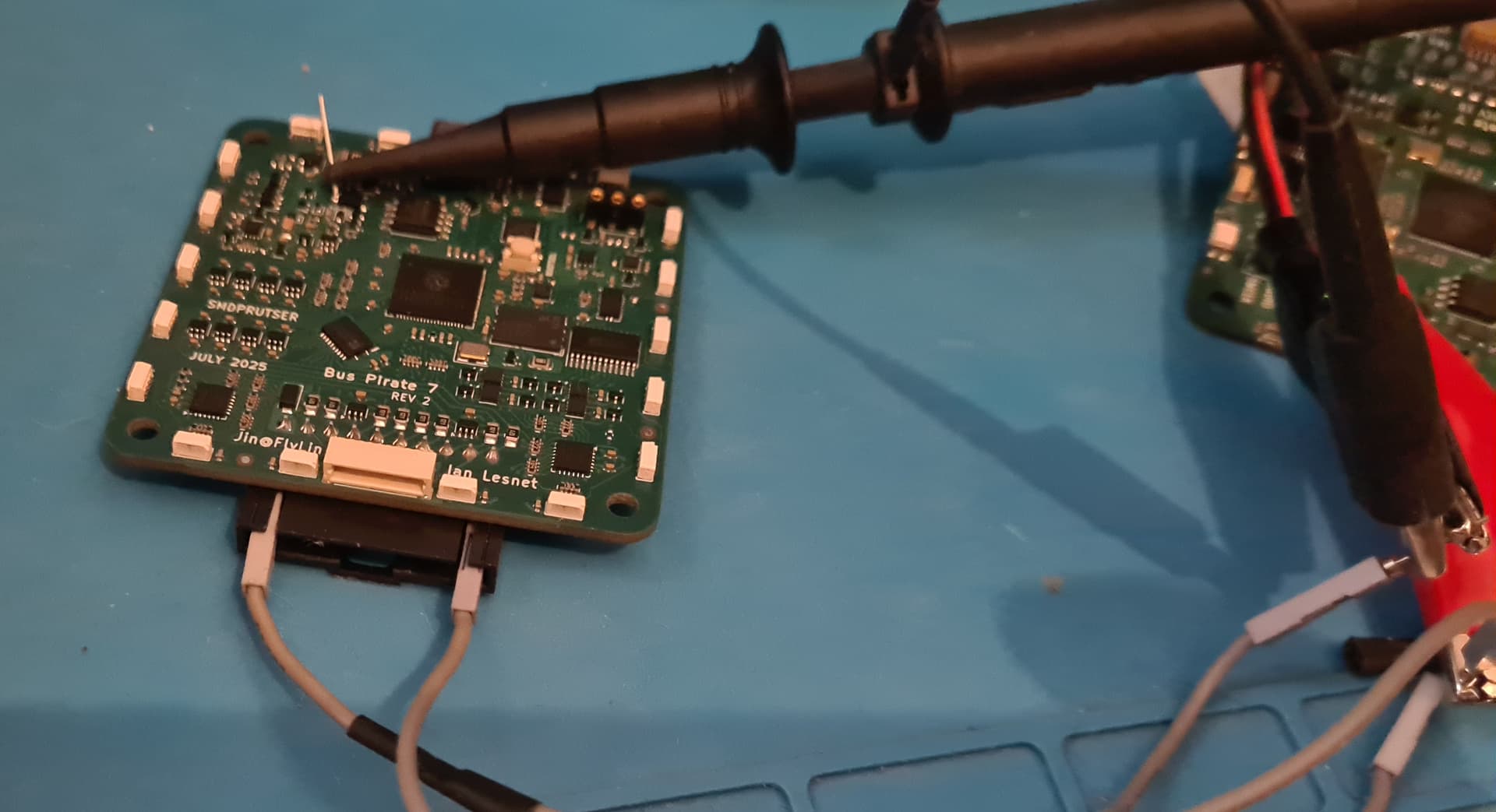
Testing VOUT protection. Tapped into the internal protected VREG output via a pad on a big diode.
While the Bus Pirate is off, VOUT protection worked perfectly up to 24 volts. The internal voltage never climbed above the baseline noise. This is the easy one though ![]()
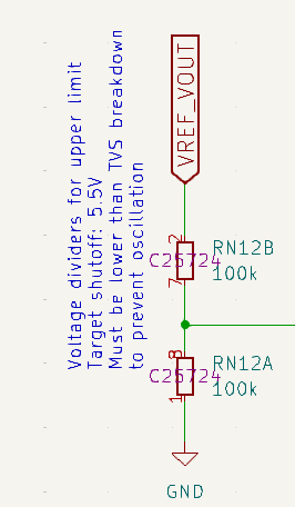
When the Bus Pirate is on, however, the internal protected VREG circuit raised to 5.4volts. It held there at up to 24 volts. It did not oscillate, a concern @electronic_eel mentions in the schematic notes.
The schematic also notes that the target shut off is 5.5volts, so I assume this was a success?
My bench supply doesn’t have a negative supply to test negative voltages, so I will need to borrow a friend’s supply.
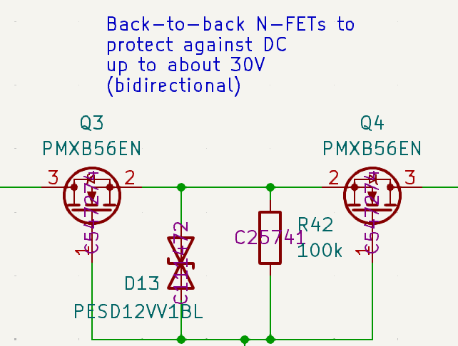
While I was poking around with a multimeter to verify voltages I made a nice snap in, I believe, Q3. After this the voltage dropped to zero (blew the FET). However, when I injected 3.3 volts directly into protected VOUT everything worked as normal. Analog voltage measurement still works, no IO buffers were blown.
I think the over voltage protection is solid.
So far we have three issues for the next revision. I have solutions to test for 2, but one is still a bit puzzling.
- Bottom LEDs need to be moved a bit further from the AUX connector to fit in the enclosure
- The VREG sinks a bunch of current when VOUT is powered externally. This can probably be solved by bringing back the one way switch in front of the VREG
- The current measurement isn’t accurate (or there is an interaction effect) when shorting VOUT to ground. This is not the case when there is an actual voltage drop (through multimeter current measurement, or an LED, etc). This is not yet solved.
Now that I have the circuit in front of me with a bit of experience using it, I need to go back and read @electronic_eel 's previous posts testing the circuit and verify that everything matches.
Showing my EE ignorance again … What result if you power the board by simply swapping ground and V+ … wouldn’t that effectively give the board negative voltage?
I mean … ground is relative, right?