Thank you for reading the docs I will rework based on that. I’m surprised it sends all fields, I thought unused fields were not sent, which makes the design a lot less efficient.
The use case is for a full I2C transaction. The idea that we send the I2C address to write and then again for a read. I’m not a fan because it is extraneous.
We could do something like assume the first byte of data out is the i2c address if the user requests read bytes.
Eta: the use case being some i2c devices will reset the address pointer if we do a stop and start instead of restart.
Ah, yes, I think I see now. Client sends address with data to write, and request a read, and the BP performs a Write-Read with repeated start, correct? (Could require this to be done in two packets.)
Here’s an example I whipped up with a MaybeBool struct wrapping a bool.
This has been a great learning opportunity, not only for you two, but also for all of us who are just watching and learning from the transparent posts. Thanks for teaching us how important it is to be willing to fail while trying, so long as we learn from that … the true essence of being a Hacker!
IIRC, many of the issues you’re experiencing also exist with protobuf. It’s really tough to define the perfect schema the first many times. And yeah, it’s really surprising to learn that default values aren’t sent.
I LOVE the hack of wrapping a scalar in a struct to be able to differentiate not_provided vs. default_value. Double points because it doesn’t actually take (much) more space(+). That same hack should also be applicable to any other scalar …
(+) I think it takes one extra ID, to identify the wrapper struct.
P.S. – Am I confused, or is flatc is for C++, while flatcc is for C.
namespace bpio;

enum StatusRequestTypes:byte{All, Version, Mode, Pullup, PSU, ADC, IO, Disk, LED}

table StatusRequest{
  query:[StatusRequestTypes]; // List of status queries to perform.
}

// returns the status queries requested in StatusRequest
// if query is empty, then all queries are performed
table StatusResponse {
  error:string; // Error message if any.
  hardware_version_major:uint8; //HW version
  hardware_version_minor:uint8; //HW revision
  firmware_version_major:uint8;//FW version
  firmware_version_minor:uint8; //FW revision
  firmware_git_hash:string; //Git hash of the firmware.
  firmware_date:string; //Date of the firmware build.
  modes_available:[string]; // List of modes available on the device.
  mode_current:string; // Current mode name.
  mode_pin_labels:[string]; // Labels for the pins in the current mode.
  mode_bitorder_msb:bool; // Bit order for the current mode (true for MSB first, false for LSB first).
  psu_enabled:bool; // Power supply enabled.
  psu_set_mv:uint32; // Power supply voltage in millivolts.
  psu_set_ma:uint32; // Power supply current in milliamps.
  psu_measured_mv:uint32; // Measured power supply voltage in millivolts.
  psu_measured_ma:uint32; // Maximum power supply current in milliamps.
  psu_current_error:bool; // Power supply fuse error.
  adc_mv:[uint32]; // ADC values in millivolts.
  io_direction:uint8; // IO pin directions (true for output, false for input).
  io_value:uint8; // IO pin values (true for high, false for low).
  disk_size_mb:float; // Size of the disk in megabytes.
  disk_used_mb:float; // used space on the disk in megabytes.
  led_count:uint8; // Number of LEDs.
  pullup_enabled:bool; // Pull-up resistors enabled.
}

// move mode string name here too?
table ModeConfiguration {
  speed_khz:uint32; // Speed in kHz for the mode.
}

//pullup is last so we can add the pull-x fields to the end of the table
table ConfigurationRequest {
  mode:string; // Name of the mode to configure.
  mode_configuration:ModeConfiguration; // Configuration for the mode.
  mode_bitorder_msb:bool; // Bit order for the mode (true for MSB first, false for LSB first).
  mode_bitorder_lsb:bool; // Bit order for the mode (true for LSB first, false for MSB first).
  psu_disable:bool; // Disable power supply.
  psu_enable:bool; // Enable or disable power supply.
  psu_set_mv:uint32; // Set voltage in millivolts.
  psu_set_ma:uint16=300; // Set current in milliamps.
  pullup_disable:bool; // Disable pull-up resistors.
  pullup_enable:bool; // Enable pull-up resistors.
  pullx_config:uint32; //configuration for pull-x on BP7+
  io_direction_mask:uint8; // Bitmask for IO pin directions (true for output, false for input).
  io_direction:uint8; // IO pin directions (true for output, false for input).
  io_value_mask:uint8; // Bitmask for IO pin values (true for high, false for low).
  io_value:uint8; // IO pin values (true for high, false for low).
  led_resume:bool; // Resume LED effect after configuration.
  led_color:[uint32]; // LED colors in RGB format (0xRRGGBB).
  printf:[string]; // string to print on terminal
  hardware_reset:bool; // Hardware reset the device.
  hardware_bootloader:bool; // Enter bootloader mode.
}

table ConfigurationResponse{
  error:string; // Error message if any.
}

table DataRequest {
  start_main:bool; // Start condition.
  start_alt:bool; // Alternate start condition.
  data_write:[ubyte]; // Data to write
  bytes_read:uint16; // Number of bytes to read.
  stop_main:bool; // Stop condition.
  stop_alt:bool; // Alternate stop condition.
}

table DataResponse {
  error:string; // Error message if any.
  data_read:[ubyte]; // Data read from device
}

union RequestPacketContents { StatusRequest, ConfigurationRequest, DataRequest}

table RequestPacket {
  version_major:uint8=0;
  version_minor:uint8=1;
  contents:RequestPacketContents;
}

table ErrorResponse {
  error:string; // Error message if any.
}

union ResponsePacketContents { ErrorResponse, StatusResponse, ConfigurationResponse, DataResponse}

table ResponsePacket{
  version_major:uint8=0;
  version_minor:uint8=1;
  contents:ResponsePacketContents;
}

root_type ResponsePacket;

/*
union RequestPacketContents { StatusRequest, ConfigurationRequest, DataRequest}
union ResponsePacketContents { StatusResponse, ConfigurationResponse, DataResponse}
table Packet{
  version_major:uint8=0;
  version_minor:uint8=1;
  request:RequestPacketContents;
  response:ResponsePacketContents;
}

root_type Packet;
*/
This is the latest flat buffer with some of the updates we discussed.
All configuration request bools are now split into enable and disable to avoid presence testing.
I also added some items I noticed in the old code that were missing (MSB/lsb, bootloader, reset, etc).
Now to get everything synced up.
Ok, so I had to make changes as I got it implemented. I’ll update when it’s all going well.
[Send Packet] Length 36
[BPIO] Flatbuffer length: 48
[BPIO] Flatbuffer received, length: 48
[BPIO] Packet Type: 1
[Status Request] Query types: 1 0
[Status Request] Version requested
[Status Request] Modes available requested
[Status Request] LED count requested
[Status Request] Pullup status requested
[Status Request] PSU status requested
[Status Request] ADC status requested
[Status Request] IO status requested
[Status Request] Disk status requested
[Send Packet] Length 532
[BPIO] Flatbuffer length: 228
[BPIO] Flatbuffer received, length: 228
[BPIO] Packet Type: 2
[Config Request] Mode changed to 'I2C'
[Config Request] Bit order set to MSB first
[Config Request] Bit order set to LSB first
[Config Request] Power supply disabled
[Config Request] PSU Voltage: 3.300000, Current: 300.000000, Override: false
[Config Request] Power supply enabled
[Config Request] Pull-up resistors disabled
[Config Request] Pull-up resistors enabled
[Config Request] IO0 set to input
[Config Request] IO1 set to input
[Config Request] IO2 set to input
[Config Request] IO3 set to input
[Config Request] IO4 set to input
[Config Request] IO5 set to input
[Config Request] IO6 set to input
[Config Request] IO7 set to input
[Config Request] IO0 set to low
[Config Request] IO1 set to low
[Config Request] IO2 set to low
[Config Request] IO3 set to low
[Config Request] IO4 set to low
[Config Request] IO5 set to low
[Config Request] IO6 set to low
[Config Request] IO7 set to low
[Config Request] LED colors: 0xFF0000 0x00FF00 0x0000FF 0xFFFF00 0xFF00FF 0x00FFFF 0xFF0000 0x00FF00 0x0000FF 0xFFFF00 0xFF00FF 0x00FFFF 0xFF0000 0x00FF00 0x0000FF 0xFFFF00 0xFF00FF 0x00FFFF
Test print to terminal
[Send Packet] Length 36
Python test script output
C:\flatpy>python flatpy.py
Opened serial port COM35 at 115200 baud
Sent 2 bytes (length header): 3000
Sent 48 bytes (flatbuffer data)
Total bytes sent: 50
Response length header: 1402 (value: 532)
Received 532 bytes
ContentsType: 2
StatusResponse:
  Hardware version: 5 REV10
  Firmware version: 0.0
  Firmware git hash: unknown
  Firmware date: Jul 21 2025 13:07:54
  Available modes: HiZ, 1WIRE, UART, HDUART, I2C, SPI, 2WIRE, 3WIRE, DIO, LED, INFRARED, JTAG
  Current mode: I2C
  Mode bit order: LSB
  Pin labels: ON, SDA, SCL, , , , , , , GND
  Number of LEDs: 18
  Pull-up resistors enabled: True
  Power supply enabled: True
  PSU set voltage: 3299 mV
  PSU set current: 300 mA
  PSU measured voltage: 3325 mV
  PSU measured current: 3 mA
  PSU over current error: No
  IO ADC values (mV): 3304, 3293, 3291, 3291, 3285, 3282, 3280, 3303
  IO directions: IO0:IN, IO1:IN, IO2:IN, IO3:IN, IO4:IN, IO5:IN, IO6:IN, IO7:IN
  IO values: IO0:HIGH, IO1:HIGH, IO2:HIGH, IO3:HIGH, IO4:HIGH, IO5:HIGH, IO6:HIGH, IO7:HIGH
  Disk size: 97.69779205322266 MB
  Disk space used: 0.0 MB
Opened serial port COM35 at 115200 baud
Sent 2 bytes (length header): ec00
Sent 236 bytes (flatbuffer data)
Total bytes sent: 238
Response length header: 2400 (value: 36)
Received 36 bytes
ContentsType: 3
Commit e8741419dd9c49da360b54ff33177404f2b1fdbc has compatible flatbuffer.fbs file, firmware, and a python script in hacks/flatpy. I think Status and Configuration tables are working as they should, and everything is connected up in the Bus Pirate firmware.
Current flatbuffer
namespace bpio;

enum StatusRequestTypes:byte{All, Version, Mode, Pullup, PSU, ADC, IO, Disk, LED}

table StatusRequest{
  query:[StatusRequestTypes]; // List of status queries to perform.
}

// returns the status queries requested in StatusRequest
// if query is empty, then all queries are performed
table StatusResponse {
  error:string; // Error message if any.
  hardware_version_major:uint8; //HW version
  hardware_version_minor:uint8; //HW revision
  firmware_version_major:uint8;//FW version
  firmware_version_minor:uint8; //FW revision
  firmware_git_hash:string; //Git hash of the firmware.
  firmware_date:string; //Date of the firmware build.
  modes_available:[string]; // List of modes available on the device.
  mode_current:string; // Current mode name.
  mode_pin_labels:[string]; // Labels for the pins in the current mode.
  mode_bitorder_msb:bool; // Bit order for the current mode (true for MSB first, false for LSB first).
  psu_enabled:bool; // Power supply enabled.
  psu_set_mv:uint32; // Power supply voltage in millivolts.
  psu_set_ma:uint32; // Power supply current in milliamps.
  psu_measured_mv:uint32; // Measured power supply voltage in millivolts.
  psu_measured_ma:uint32; // Maximum power supply current in milliamps.
  psu_current_error:bool; // Power supply fuse error.
  pullup_enabled:bool; // Pull-up resistors enabled.
  pullx_config:uint32; //configuration for pull-x on BP7+
  adc_mv:[uint32]; // ADC values in millivolts.
  io_direction:uint8; // IO pin directions (true for output, false for input).
  io_value:uint8; // IO pin values (true for high, false for low).
  disk_size_mb:float; // Size of the disk in megabytes.
  disk_used_mb:float; // used space on the disk in megabytes.
  led_count:uint8; // Number of LEDs.
}

// move mode string name here too?
table ModeConfiguration {
  speed_khz:uint32; // Speed in kHz for the mode.
}

//pullup is last so we can add the pull-x fields to the end of the table
table ConfigurationRequest {
  mode:string; // Name of the mode to configure.
  mode_configuration:ModeConfiguration; // Configuration for the mode.
  mode_bitorder_msb:bool; // Bit order for the mode (true for MSB first, false for LSB first).
  mode_bitorder_lsb:bool; // Bit order for the mode (true for LSB first, false for MSB first).
  psu_disable:bool; // Disable power supply.
  psu_enable:bool; // Enable or disable power supply.
  psu_set_mv:uint32; // Set voltage in millivolts.
  psu_set_ma:uint16=300; // Set current in milliamps.
  pullup_disable:bool; // Disable pull-up resistors.
  pullup_enable:bool; // Enable pull-up resistors.
  pullx_config:uint32; //configuration for pull-x on BP7+
  io_direction_mask:uint8; // Bitmask for IO pin directions (true for output, false for input).
  io_direction:uint8; // IO pin directions (true for output, false for input).
  io_value_mask:uint8; // Bitmask for IO pin values (true for high, false for low).
  io_value:uint8; // IO pin values (true for high, false for low).
  led_resume:bool; // Resume LED effect after configuration.
  led_color:[uint32]; // LED colors in RGB format (0xRRGGBB).
  print_string:string; // string to print on terminal
  hardware_bootloader:bool; // Enter bootloader mode.
  hardware_reset:bool; // Hardware reset the device.
}

table ConfigurationResponse{
  error:string; // Error message if any.
}

table DataRequest {
  start_main:bool; // Start condition.
  start_alt:bool; // Alternate start condition.
  data_write:[ubyte]; // Data to write
  bytes_read:uint16; // Number of bytes to read.
  stop_main:bool; // Stop condition.
  stop_alt:bool; // Alternate stop condition.
}

table DataResponse {
  error:string; // Error message if any.
  data_read:[ubyte]; // Data read from device
}

union RequestPacketContents { StatusRequest, ConfigurationRequest, DataRequest}

table RequestPacket {
  version_major:uint8=0;
  version_minor:uint8=1;
  contents:RequestPacketContents;
}

table ErrorResponse {
  error:string; // Error message if any.
}

union ResponsePacketContents { ErrorResponse, StatusResponse, ConfigurationResponse, DataResponse}

table ResponsePacket{
  version_major:uint8=0;
  version_minor:uint8=1;
  contents:ResponsePacketContents;
}

root_type ResponsePacket;

/*
union RequestPacketContents { StatusRequest, ConfigurationRequest, DataRequest}
union ResponsePacketContents { StatusResponse, ConfigurationResponse, DataResponse}
table Packet{
  version_major:uint8=0;
  version_minor:uint8=1;
  request:RequestPacketContents;
  response:ResponsePacketContents;
}

root_type Packet;
*/
Next I’ll move onto the data request and get it going in I2C.
Quick note: I’ve done some testing and found some bugs. If you try to do a data request there are two notes:
Mode configuration is not handled yet, so the mode speed is 0khz and you get timeouts. Solution: enter mode and set the speed in the terminal before running the script, this will populate the mode config with some default values.
I2C errors cause bus pirate to crash. This is due to placement of the bpio_DataResponse_start(B); function. I’ll push a bug fix later.
Some thoughts, using the `StatusRequest` as an example.
This request takes as input an array of status types to request:
All
Version
Mode
Pullup
PSU
ADC
IO
Disk
LED
Requesting All likely doesn’t make sense if this API is intended to be versioned (e.g., adding other status types to the enum later).
Similarly, should there be a query for what status types are available? (e.g., also for versioning)
StatusResponse table … not clear as written which fields correspond to which of those enum types. If sticking with this general API, consider having a table corresponding to the data that each of those enum’d.
table StatusResponse {
    version : StatusVersionResponse;
    mode : StatusModeResponse;
    pullups : StatusPullupResponse;
    psu : StatusPsuRepsonse;
    adc : StatusAdcResponse;
    io : StatusIoResponse;
    disk : StatusDiskResponse;
    led : StatusLedResponse;
}
Some of those things aren’t really status … they don’t update over time. firmware info, led count … maybe these should be in separate command?
Each mode should have its own (set of) commands, including for configuration. Don’t try for a single ConfigurationRequest to handle all modes … that way madness lays. Examples of Why:
Clients get to see only (in autocomplete) relevant fields, and the option for per-field documentation.
Modes won’t all follow that format … consider a mode where the IR plank is used … most of the fields in that configuration request don’t make any sense. bitorder settings are a great example … not useful for IR…
Create smaller pieces … even if initially the communication is more “chatty”. e.g., psu settings should be their own table / command. Not only will this simplify both testing AND implementation, it makes it much easier for a client to use the API.
I’ll have more later today, but here’s an exercise for you:
Write some pseudo-code as a client that you’d want it to look like, without worrying about the flatbuffers API.
Then, make those APIs work … and if you get stuck, then consider how to change the client API. Don’t start at flatbuffers … start with the client API.
Here’s some of my initial thoughts on how I’d like the API to look, overall. This is just pseudo-code, language-agnostic, strawman as an example starting point. What would a client do when using a buspirate?
long thoughts collapsed for thread sanity
// 0. enumeration is done via OS-specific manner.
//    and so just presume an implied handle to the device
//    or object representing the device.

// 1. First thing client will likely do is get immutable hardware
//    info ... stuff that doesn't change like number of LEDs,
//    model of the BP, serial number, etc.
get_HardwareDetails( hardware_details );

// 2. What firmware and flatbuffer-based-API is running on the device?
get_ApiVersion( semver_api_version ); // exit if major_v > expected
get_FirmwareVersion( firmware_info ); // optional

// 3. Is the device already in the desired / supported mode?
get_CurrentMode( mode );

// 4. If not a mode client supports, reset to known-good state
reset_to_HiZ_mode();
get_CurrentMode( mode );

// 5. switch to mode foo, and configure
//    global (non-foo-specific) settings
switch_to_mode_foo( const foo_configuration );
global_configure_psu( const psu_configuration );
global_configure_pullups( const pullup_configuration );
global_fala_enable( const fala_configuration );

// 5. Client can then starts per-mode interaction....
foo_task( ... )

// 6. and loop to update status relevant to that mode
foo_get_status( ... )
Later, if lots of clients do X, then Y, then Z … can create an updated command that does all three, and re-uses the building block tables that were each single-function. e.g.,
Avoid having scalars and tables in the main / root request message … use a union of those per-command tables.
Avoid scalars, (a) unless there will never be a need to differentiate between the value not being provided vs. the default value, or (b) unless API versioning will be done through use of new tables. This is because sending default value == nothing sent =~= field was not supported/known.
Avoid mixing dynamic data (e.g. pin readouts, current mode) with constant data (e.g., model, led counts, firmware version, etc.) … clients ask for those for different reasons.
It is of course my preference to design everything as discrete blocks. There are a couple things about flatbuffers that nudged me in this direction, at least for initial development.
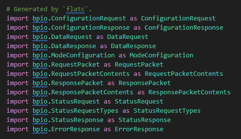
The flatbuffer tooling is a lot. A lot of files, a lot of functions. Every new table brings in a slew of new functions, and they’re very sensitive about naming (at least on the C side).
For the current 3 tables plus wrapper table, this is how many includes are used in the flatpy.py test script. That’s not the end of the world, but it does take me an hour to two to sync everything back up after making a slight change.
My plan is to figure out how flatbuffers work (about half way there), get all the internal functions pulled together in the Bus Pirate firmware, and then consider the final implementation when I have a better overall understanding of how it all actually works.
BPIO2 can display detailed debugging data in the Bus Pirate terminal. Enable this by setting "bpio_debug_enable":1 in your BPCONFIG.BP JSON file on the Bus Pirate internal storage. Remember to reboot for this setting to take effect. If you don’t have a config file (or bpio_debug_enable), simply got to the config menu c, then hit x to exit. The file will be created or updated to the latest format. (added to docs)
I2C transaction should be logically solid now, with extensive debug info available.
bpio_handler and bpio_config (and dummy functions) are now in the master modes struct. Modes without bpio support return an error message view the flatbuffer interface.
The mystery crash was due to not using free(buff) after sending packets. It’s solid for a 100+ query test now.
I’ll work on the protocol configuration packet next, that’s a huge missing piece, then we can bring in SPI and probably 1-Wire.
ETA:
table ModeConfiguration {
  //1wire : no config
  //uart: speed, data bits, parity, stop bits, flow control, signal inversion
  //hduart: speed, data bits, parity, stop bits
  //i2c: speed, clock stretch
  //spi: speed, data bits, clock polarity, clock phase, chip select
  //2wire: speed
  //3wire: speed, chip select
  //dio: none
  //LED: submode,
  //INFRARED: submode, TX modulation, RX sensor
  //jtag: none
  speed:uint32; // Speed in Hz or baud for the mode.
  data_bits:uint8; // Data bits for the mode (e.g., 8 for UART).
  parity:bool; // Parity for the mode (true for even parity, false for no parity).
  stop_bits:uint8; // Stop bits for the mode (1 or 2).
  flow_control:bool; // Flow control for the mode (true for enabled, false for disabled).
  signal_inversion:bool; // Signal inversion for the mode (true for inverted, false for normal).
  clock_stretch:bool; // Clock stretching for I2C mode (true for enabled, false for disabled).
  clock_polarity:bool; // Clock polarity for SPI mode (true for high, false for low).
  clock_phase:bool; // Clock phase for SPI mode (true for leading edge, false for trailing edge).
  chip_select_active_low:uint8; // Chip select active (0=Active High, 1=Active Low) for SPI and 3-wire modes.
  submode:uint8; // Submode for LED and INFRARED modes (e.g., "RGB", "IR TX", "IR RX").
  tx_modulation:uint8; // TX modulation for INFRARED mode (true for enabled, false for disabled).
  rx_sensor:uint8; // RX sensor for INFRARED mode (true for enabled, false for disabled).
}
This is probably going to be controversial, but I put all the possible mode configuration options into a single table.
typedef struct {
    bool debug;                 // Debug flag for BPIO
    uint32_t speed;              // Speed in Hz or baud for the mode
    uint8_t data_bits;           // Data bits for the mode (e.g., 8 for UART)
    bool parity;                 // Parity for the mode (true for even parity, false for no parity)
    uint8_t stop_bits;           // Stop bits for the mode (1 or 2)
    bool flow_control;           // Flow control for the mode (true for enabled, false for disabled)
    bool signal_inversion;       // Signal inversion for the mode (true for inverted, false for normal)
    bool clock_stretch;          // Clock stretching for I2C mode (true for enabled, false for disabled)
    bool clock_polarity;         // Clock polarity for SPI mode (true for high, false for low)
    bool clock_phase;            // Clock phase for SPI mode (true for leading edge, false for trailing edge)
    uint8_t chip_select_active_low;         // Chip select active (0=Active High, 1=Active Low) for SPI and 3-wire modes
    uint8_t submode;             // Submode for LED and INFRARED modes (e.g., "RGB", "IR TX", "IR RX")
    uint8_t tx_modulation;       // TX modulation for INFRARED mode (true for enabled, false for disabled)
    uint8_t rx_sensor;           // RX sensor for INFRARED mode (true for enabled, false for disabled)
} bpio_mode_configuration_t;
Then I put all the table fields into a configuration struct and pass it to the mode configuration function.
Making a table for each mode may be slightly more efficient, but it results in tons and tons of code both in the tooling and to work with.
Using individual mode config structs may be slightly more efficient, at the cost of a much more complex design tracking where to put what.
Another option would be to bless each mode with knowledge of flatbuffers, but that seems like a poor separation of major areas of code.
I’m sure it will come together over time.
Next steps are probably bringing up SPI and then verifiers.
bpio_configuration_request("1WIRE", 100000)
bpio_data_request(True, False, [0xcc, 0x4e, 0x00, 0x00, 0x7f], 0, False, False)
bpio_data_request(True, False, [0xcc, 0x44], 0, False, False)
# delay 800ms to allow the device to process the command
import time
time.sleep(0.8)
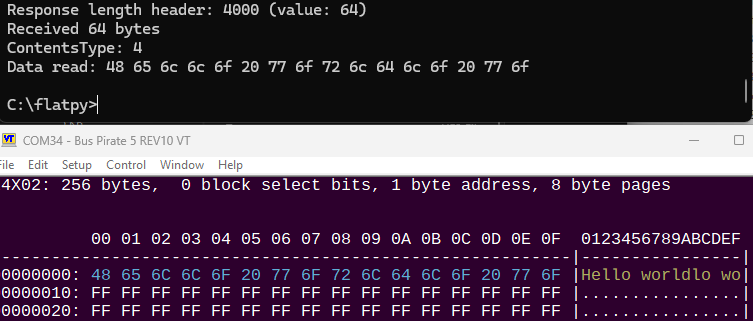
bpio_data_request(True, False, [0xcc, 0xbe], 9, False, False) # Read 9 bytes
Data read: c3 01 00 00 7f ff 0d 10 d7
Reading 1-Wire temperature sensor.
Weird bug - the MOSI pin label on the display is not drawn in flatbuffer mode. It’s on the terminal, and it shows if you manually enter the mode. I cannot figure this out, they all use the same functions.
Next I’ll deprecate the old binio code, which means updating some stuff in the legacy BBIO binmode. Then, I think I’ll push to main for anyone who wants to beta test it.
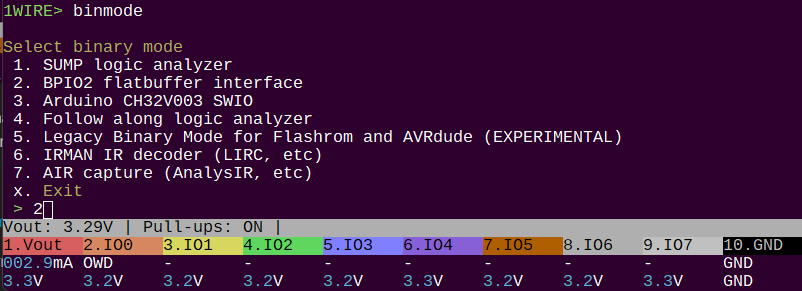
“BPIO2” flat buffer binary interface is now available in the main branch autocompile. There’s still work to do, but I wanted to put out a “stable” release for anyone interested in testing.
My next step is probably to write a simple python wrapper for the flatbuffer tooling, then circle back and do a round of updates to the flatbuffers. At some point we need to settle on a framing method, preferably nicer than “2 byte length prefix” but not so complicated nobody will use it.
Yep! The flatbuffer library method that finishes off the data to send and appends a length prefix uses 4 bytes!
I did manage to crash the current firmware before I got it working, but I’ll undo my changes a bit and see, can’t remember now if that was with a 4-byte length (3 bytes all zeroes) or something else I tried in between.