There are three different “finish” methods on the flatbuffer builder struct, in the Rust library at least, only one of which adds the length prefix. I’ll check the API docs after lunch to see if that’s common in their libraries.
The finish-with-size-prefix methods across the flatbuffer libraries I looked at all use 4 bytes, this comes from the internal UOffsetT type (unsigned offset).
bpio_StatusResponse_end(B);
I found some _start_with_size functions in the C library, but not end. I’ll play with the start_with_size and see what it does ![]()
bpio_client.zip (116.5 KB)
Here is a simple demonstration Python module for interaction with protocols. It lacks any general access to status or configuration, but it does have a simple method to setup and use a bus.
- Configure your serial port in example.py
- Set one of the demos to “True”
- run example.py
# Create client
client = BPIOClient('COM35')

# Get status
client.status_request()

# I2C Example
i2c = BPIOI2C(client)
if i2c.configure(speed=400000, pullup_enable=True, psu_enable=True, psu_voltage_mv=3300, psu_current_ma=0):
    #scan for devices
    devices = i2c.scan()
    if devices:
        print(f"Found I2C devices: {', '.join(f'0x{addr:02X}' for addr in devices)}")
    else:
        print("No I2C devices found.")
    # read 24x02 EEPROM
    data = i2c.transfer(write_data=[0xA0, 0x00], read_bytes=8)
    if data:
        print(f"Read data: {data.hex()}")
    else:
        print("Failed to read data.")
Here’s the example to scan for I2C devices and read from a 24x02 EEPROM.
i2c.configure(speed=400000, pullup_enable=True, psu_enable=True, psu_voltage_mv=3300, psu_current_ma=0)
This line enters I2C mode, configures the speed, enables pullups, enables and configures the PSU. Any of the ConfigurationRequest fields can be passed.
data = i2c.transfer(write_data=[0xA0, 0x00], read_bytes=8)
Transfer arranges one full I2C transaction. Start, write address, write data, restart, read address, read data, stop.
Read data: 48656c6c6f20776f
Display the first 8 bytes of the EEPROM.
Well, that’s kind of slow
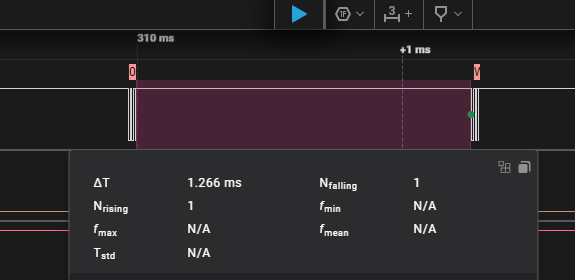
The i2c.scan() function searches for I2C addresses. Initially each packet was spaced by 5-6ms, dreadfully slow. I updated the python script to keep the serial port open while in use (instead of opening for each command) and that went down to 1.3ms (still achingly slow). Packet by packet bit banging max out at less than 500hz, ouch!
I’m not sure where the delay is taking place. I assume a bit of it is Python, but most of it is in the Bus Pirate.
The packets are much longer than the data read or write, it seems like 30-60 bytes of overhead, but we should be able to pump ~800Kbyte/S+ through the USB CDC so 255 * 60byte * 2 packets isn’t enough to saturate it.
On stack overflow there is a discussion about the (flatbuffers, protobuffer, cap’n’proto) buffer initialization taking the most time. Indeed we allocate a new buffer on each packet received, so this may be the issue. Something to look further into.
Also noted some suggestions to compile in release instead of debug. Tried this, and yeah the bpio interface crashes when receiving the first buffer. This is probably a hint of bad error handling (flatcc_builder_int() returns unhandled -1 error code).
To do
- Add “getter and setters” for Status and Config fields (Python example)
- Improve error passing and handling in firmware and client (especially I2C, 1WIRE RESET)
- Speed? Packet size and complexity? Buffer initialization? Release build failure?
I’ve stuck the different crashes I’ve caused in a Github issue. All cases of (obviously, in retrospect) malformed input from the user.
The flatcc library seems to depart from the conventions of the in-tree ones. Perhaps there’s no with-size finish function because flatcc_builder_finalize_buffer takes a size_t out param? (source here)
DataRequest timing:
- Receive data: 250us with queue (200us bare metal)
- Request Packet as root: 7uS
- flatcc_builder_reset: 25uS
- DR:decode request: 40uS
- I2C wire time: 29uS by Logic Analyzer (40uS by timing)
- DR: encode response: 150uS
- Send packet: 150uS queue (200uS bare metal)
~650uS total. Timing the whole thing (instead of in parts) I found ~750uS per transaction, so that seems right.
USB RX/TX is defo the bulk of the time. When using the queue core 2 handles the USB overhead and it is slightly faster to send, bare metal is using the tinyusb functions directly. I’m not sure there’s any getting around that without moving to a bulk interface which makes everything exponentially more difficult for users to work with.
That still leaves ~350-450uS unaccounted for, possibly on the PC side.
I guess this works for bulk transfers where lots of data goes in few packets, but it almost seems unusable for small data transfers? Let’s have a look.
Big transfer time
Let’s simulate the biggest I2C EEPROM 24xM02 2 Mbit 262144bytes. 1024 pages of 256bytes.
        start_time = time.time()
        # read 2Mbit EEPROM
        for addr in range(0, 1024):
            data = i2c.transfer(write_data=[0xA0, 0x00], read_bytes=256)
            if not data:
                print("Failed to read data.")
        end_time = time.time()
        print(f"I2C transaction took {end_time - start_time:.4f} seconds")
I2C transaction took 9.0423 seconds
- We’re getting ~29,127 bytes per second.
- The theoretical maximum (9bits per word, ignore start and stop) at 400kHz I2C is 44,444 bytes per second.
- 1024 packets/9seconds = 113 packets/second
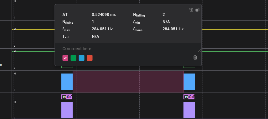
- 2ms delay between bus operations (by logic analyzer) * 113 packets = 226ms
We’re spending 25% of our time on USB (and other overhead).
Theoretical read from 128mbit SPI flash chip, 256byte page writes, just rough guestimation:
- 10MHz bus speed, 1,250,000 bytes/second absolute max
- Up to 4882 pages per second, 0.2ms per page
- 2ms between page delay + 0.2ms = 2.2ms per page = 454 pages/second
- 116,224 bytes per second
- 16,000,000/116,224
- ~138seconds per chip
For anyone who has flashrom experience, is ~2 minutes a decent speed to read a 128Mbit (16MB) SPI flash chip?
As a comparison it takes 1m15s to dump a 128mbit winbond flash chip at ~9MHz using the flash command in the terminal, and the SPI NAND (onboard storage) is probably the bottleneck there.
Any thoughts? Would USB bulk transfers reduce the between packet delay (internet suggests not really, but inconclusive).
2 minutes a decent speed to read a 128Mbit (16MB) It’s good in my opinion
The problem is that we still don’t know how much the overhead from programs like flashrom — with their internal layers and architecture — increases the latency
Great. If the speed isn’t going to get us laughed at, then I’ll stop looking for ways to optimize it and continue with device error reporting and validation and error handling in the firmware. These are two very weak areas.
I’m having trouble performing just an I2C read. I have a data request with the I2C read address in the write vector, but nothing else, like so:
DataRequest {
  start_main: true,
  start_alt: false,
  data_write: [ 0xA1 ],
  bytes_read: 4,
  stop_main: true,
  stop_alt: false,
}
And the result is a Write-Read, but with no bytes written except the corresponding 0xA0 write address, followed by the (correct) read. The debug print output is as follows:
[I2C] Performing transaction
[I2C] START
[I2C] Writing 1 bytes
[I2C] Write address 0xA0
[I2C] RESTART
[I2C] Read address 0xA1
[I2C] Reading 4 bytes
[I2C] STOP
You are correct. The I2C logic for handing the address is wrong. I pushed a fix, but I’m not sure how the current approach is going to age long term… Let’s see how this goes, but that i2c_address field might be needed after all.
Brilliant, thanks. I’ll give it a go this evening.
The last variation on an I2C transaction I need to check/implement are reads/writes with no start, no stop, and no address (ie, continuing an already-started transfer). Perhaps this will flush out any last problems?
Lots of housekeeping today. The bpio interface is much more resilient to broken packets and bugs.
Firmware
- Verification of request packet
- Fixed crash on error packet
- Fixed I2C read without write
- Fixed I2C single byte read (I2C scan)
- Additional error checking
- Timeout if packet not received in 500ms.
Python interface example
- Added BPIOBase class with get and set functions for all status and configuration requests
- Refactored client code to be more modular and reusable
- Consolidated error packet and packet type handling
- Updated the I2C example
I’m still not super happy with everything, but at least we have a working first prototype to rebuild.
SPI flash read speed test time!
With 256 bytes per read, there is 3.5ms of usb + other overhead between packets.

With 256 byte reads we get about 65KB/s average speed and a 16MB flash chip takes ~250 seconds to read. According to @dreg the old BBIO top speed (in general use, not flash specific modes) was 90 seconds for 4MB. Old BBIO1: 360 seconds, new BPIO2: 250 seconds. Seems like a win, especially with the overhead of the flatbuffers in the mix.

Let’s increase the read size to 512bytes: chip dumps in 211 seconds.
With 1024 byte read size (not possible with current setup) we might be able to get under 3 minutes.
If you’d like to try your own speed test, the dump I used is in hacks/flatpy/example.py in the firmware repo.
TO DO:
Feel sweet relief that it’s not as slow as molasses- Framing
- Pass errors from bus up to host
- Investigate and optimize ram usage for maximum read/write sizes (target 1024 bytes, maybe more if big buffer is available? Perhaps this should be part of the status and config tables? Status show current max read/write size. Is big buff available, try to claim it.)
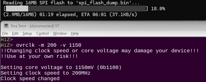
Very good speed considering everything that’s happening under the hood — congrats! @Ian try overclocking to 240 MHz (no need to tweak voltages on the RP2350 or RP2040 for that speed) and run the tests to see how much we gain.
Ha! Yeah, I’ll try an overclocked test, but I suspect the delay is the actual USB exchange which won’t really be impacted that much by overclocking.
I’m curious to see how much performance we gain percentage-wise with the overclock — 240 MHz is a good compromise, and USB and everything else should still work without issues.
Overclocked at 200MHz, just barely faster than 125MHz @ 30.9 KB/s (this is with COBS enabled both directions). The delay really does seem to be mostly in the USB timing. I did not try it without COBS enabled.
Have you gotten any hard perf / profiling data (how much time spent in each function, ISRs, etc.)?
Segger SysView would be an example. Segger Ozone can do sampling based profiling (included with JLinkPlus or higher). Are there good free tools for profiling bare-metal, OSS development?
- If USB timing is the issue, and the profiling data shows lots of time waiting for the other side, then perhaps updating the client to have 2-3 flatbuffer messages encoded while the current flatbuffer message is being worked on can reduce delays?
- There should be an API to re-use an already-existing allocated flatbuffer. Not sure if that’s better/faster than creating one from scratch.
I have timed each line. Not sure it’s totally accurate, but the times are in the comments in the source (not updated to today!). We do reusethe flat buffer, and use reset to clear it, but I still need to look how it uses the stack.
Spent a few hours trying to get a handle on the memory usage going on in bpio2.
While trying to track down how and where flatbuffers is getting its RAM, I learned that PICO SDK supports malloc out of the box. This is something I did not know and find a bit dangerous. I’d much prefer to allocate a block of ram myself, and it does seem possible, but I haven’t figured out how.
Instead, I’m going to look at eliminating some of the intermediate buffers we’re using by reworking the data request handling.


