I’m looking for help, just received the Buspirate5 and tried to connect to uart port in the pcb of one router I had, I searched pins and wit external logic analyzer confirmed uart protocol, pinout and baudrate.
I hooked up the buspitare and saw the boot process beautifull, the problem started when I tried to ‘write’ data, as is completely ignored,
I tried to do a looptest with same result, also wrote a simple python script to try to communicate with a raspberry, same result: I’m able to read, but can’t write at all
I tried to write in bridge mode, here no matter wich key is pressed that is simply ignored.
From main menu, changing to “uart” mode, if Iwrite [“hola”:
Did you either connect a power supply with the wanted transmit voltage (for example 3.3V) to the VOUT pin or enable the internal programmable power supply (“W” command)?
Without one of those steps the BusPirate wouldn’t know what voltage to use to transmit.
Be sure to check that there is a power source for the pins as mentioned by @electronic_eel .
If you want dead simple FT2232H like bridge, type the “bridge” command in the terminal. Press the button to exit when you’re done.
If neither of these works for you, try a loopback test by connecting tx and rx with a wire. Enable a power supply with the W command, then “bridge” and type something. It should echo back as you type.
Thanks, I keep trying against an Arduino Due, and with this one looks like it’s working…
I don’t know, that’s a little bit weird, but at least now I know the bus pirate is ok.
Let me take advantage from this thread, and ask another doubt…
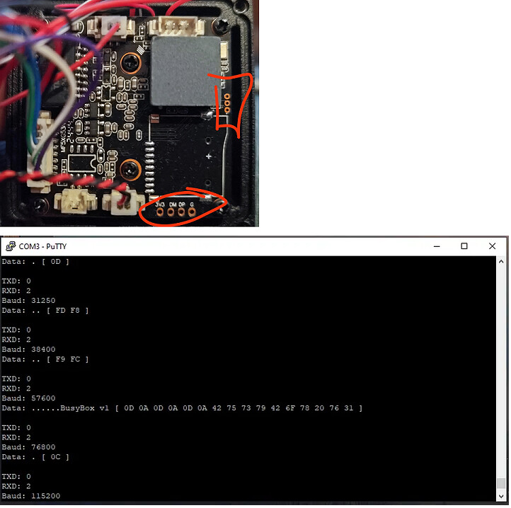
I have a IP cam that is not working, I mean it is working up to the moment the lan cable is connected and the network stack is configured the boot loop starts, so I decided is a good target to investigate it… I dismantled it and saw in the PCB 4 holes, I though we’re for uart, but the silk markings say DP and DM, so one may think is for USB but I was unable to decode any USB nor UART communication with the logic analyzer. What is keeping me away to solder and connect directly a USB cable to that points are the fact that it also has markings of 3.3v in vcc and the measured voltage where also 3.3v, so I’m afraid that connecting USB will harm the camera by over voltage…
Does the bus pirate have a USB mode?
I would try to find out what is causing the boot loop:
Is it just that the network is connected on the ethernet layer?
Is it some data it gets over the network, like DHCP?
How does it behave if you configure some completely different network via DHCP?
Is it some data it expects over the network, but doesn’t get, like DHCP or an internet connection?
So I’d start with setting up a dedicated network port on a machine and connect it just to this camera with a direct ethernet cable, no other switch, router, whatever in between. Then set up things like a DHCP server, IP forwarding and such. All the while investigating with tcpdump what is going on on this dedicated port.
This could be either a device port (upstream facing port) or host port (downstream facing port). Both things are not uncommon for a IP cam to have. A debug console or linux shell is what you want want, but both are not that common over usb on such devices.
If you want to go this route I’d continue searching for a serial connection. Maybe it is just on some test pins and not on a thick header?
No. Maybe there will be one with an additional plank in the future.
I had done mostly the same as my router is fully customizable.
Got wireshark traces and in the exact moment the dhcp server send the IP in the arp response the cam reboots, that’s why I was searchivn for the uart port to ‘see’ in detail what was happening.
Maybe that 4 pads was meant for an unpopulated USB conneciton and the other 3 is for SWDIO?
Did the Buspirate has a UART scanning mode as the extinct JTAGulator?
I mean maybe there is a script or macro that does the same: testing if the connected pin is uart, wich one is ecah and the baudrate is working
There currently is no UART autobaud scanning mode. It would be nice to have this though.
But I don’t think you need this fully featured one to identify a UART-TX:
Connect the pins in question to the BusPirate.
Then try the “logic” command or the full sigrok/pulseview based logic analyzer.
You should see some toggling of the UART-TX pin and be able to identify it this way. As a next step you can now try different baudrates to decode the data. Or when using sigrok/pulseview you can let it guess and decode on the PC.
This time the terminal allows me to write so the initial topic is solved, now I have to search info abot the bootloader or the firmware to know how to stop in login(it ask for yser ad password but there is only one or 2 seconds to do so).
Now I can see clearly that somethig bad is happeing and is probably because of the firmware itself, once the boot process is finished this message is shown over and over again:
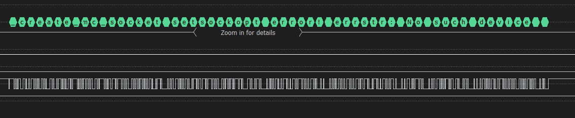
_create_mc_socket setsockopt error! errstr: No such device
[ERROR] [Socket] [1970-01-01 08:03:13] (utl_socket_add_membership:1119) socket 30 set ADD_MEMBERSHIP failed: error=19, No such device

[  194.008329] libphy: linkdown . reset phy...
[  194.020419] AFE driver [Raw] : [100M] : [10M] = [101f] : [10] : [1f]
_create_mc_socket setsockopt error! errstr: No such device
In the moment I connect the network cable a sigterm segmentation error pops up and the camera reboots:
_create_mc_socket setsockopt error! errstr: No such device
udhcpc: sending discover
udhcpc: sending select for 192.168.3.18
udhcpc: lease of 192.168.3.18 obtained, lease time 600
Setting IP address 192.168.3.18 on eth0
<DEBUG> [     NET] [1958] IFLA_IFNAME=eth0
<DEBUG> [     NET] [1963] IFA_LABEL=eth0
<DEBUG> [     NET] [2010] eth0 set ip 192.168.3.18, broadcast 192.168.3.255
Deleting routers
route: ioctl 0x890c failed: No such process
Adding router 192.168.3.1
[DEBUG] [AF] [1970-01-01 08:00:12] (_af_init:233) AF Window HOffset = 640, VOffset = 360, HSize = 1280, VSize = 720

[DEBUG] [AF] [1970-01-01 08:00:12] (_af_init:242) AF init ok

<DEBUG> [     NET] [2103] set gateway 192.168.3.1
Recreating /tmp/etc/resolv.conf
 Adding DNS server 192.168.3.1
route: ioctl 0x890b failed: File exists
enter night mode
clear pd alarm
Segmentation fault
starting pid 360, tty '': '/bin/umount -a -r'
Sent SIGKILL to all processes remounted read-only
Requesting system reboot
Time to research for the root password over the network
I got root access to the actual firmware, and found everything I need to identify its manufacturer and model ‘Vatilon PA4’ sadly they only have the same firmware version in theri downloads webpagethe cam has already installed onto and not even archive.org have the previous version…
So I “”“fixed”“” it by disabling DHCP and setting a fixed IP address, it does not prevent the bootlopp of the camera is powered on with ethernet cable, but alows normal boot and working if I put the power cable and after a few seconds the ethernet one… maybe udhcpd is started at boot before actual disabling it, IDK, but at least happy ending “camera recovered”
When you got root access - can you modify the image permanently or is writing it a more complicated thing (like squashfs, cpio or similar)?
If you can modify the image permanently you could try to symlink the udhcpd (or other dhcp client programs) to /bin/true so they don’t get executed, but don’t cause an error.