Yes, PSRAM good choice for LA. Also for PWM/PDM. Only need check maximum speed.
2 Likes
Wow! Is this the first BP5+ third-party board?
@ian … for PSRAM, there is significant difficulty in auto-detection of PSRAM. I had a long-running issue thread with the Espressif folks about this on Github, begging them to simply reserve a few bytes of OTP to store the PSRAM settings in an Espressif-defined location, so that a common bootloader could be used for both PSRAM and non-PSRAM chips. (lots of requests for this, not just me)
If integrating this, it should be one of the things added to the OTP directory information added during manufacturing. Then, the code can use the PSRAM (or not) based on the stored OTP data.
1 Like
Would these kinds of issues also affect the BusPirate or isn’t this something that just affects the Espressif chip architecture?
For example the RP2350 would always boot from the NOR flash, no matter what, because the chip select of the PSRAM would be disabled by default with a pullup. Only when the BP firmware is running it can decide if it wants to use the PSRAM for some feature like the logic analyzer.
And please forgive me my ignorance - but wouldn’t the BP firmware then be able to autodetect it? Like write something at an address and then try to read it back? If there were no PSRAM you should get back all zeroes or ones, depending if you used pullups or pulldowns on the data lines.
1 Like
No problem putting the capacity in OTP, but it would make upgrades hard when the 128MBIT version is released.
No problem doing a test write and read out of range either.
The PSRAM specced supports the 0x9f read ID command and responds with a manuf. ID (0x0D), KGD (?, 0x5d), density code (0b010, and a long EID (undefined? unique chip id?). I checked the 16MBIT version and the density code is indeed different (0b000), however I do not know how easy it is to get the 9f info (SPI mode only) when the chip is initialized as part of the QSPI/RP address space.
This is probably very similar to when you want to read the ID codes of the NOR flash (which I already have programmed myself): you disable the XIP, send some commands manually and then re-enable the XIP again. The code for doing so must be loaded into ram first, because you can’t access XIP mapped code while XIP is disabled.
So this is mostly about linking functions into the correct sections and ensuring that no other function is running on the other core or irqs while doing so.
1 Like
Not capacity … it was the PSRAM bus type. Found the issue I opened.
We failed to persuade...
As is obvious from the thread, I first failed to explain that I was only asking them to reserve an official set of OTP fuses, so that the community could improve the situation. Unfortunately, they misunderstood the request as asking them to burn the OTP at factory.
Later, when the understood the request was to reserve the OTP fuses, they failed to understand how setting this in OTP was better than just writing the proper firmware to the device.
Folks from many projects (Tasmota, ESPEasy, WLED, etc.) tried to express the usefulness of having a single bootloader.
In the end, Espressif did not understand the benefit this would provide at essentially zero cost to them.
So, it’s not the capacity … it also had to do with the type of the PSRAM (QSPI vs. OSPI) and the type of the flash (QSPI vs. OSPI). There’s a separateissue on that topic. But the short version: To have a single bootloader (or other binary) supporting many chip + FLASH + PSRAM options, it’s essentially mandatory to store at least the bus type for each in the OTP.
2 Likes
Ok, I see.
But for the BP there is no external bootloader, we are using what RasPi provides and limit the types of NOR flash supported. In the full firmware we have enough space and time to do more elaborate probing regarding PSRAM.
SPI, QSPI, OSPI,… all start out as regular SPI before the more advanced modes are activated and have a very basic, but common command set - at least to my knowledge. So for example the 0x9f read ID command should work on all of them. Based on the result you should be able to implement a small decision tree that arrives at the correct parameters to talk to the memory.
It is not that I’m against reserving space for this - when you rely on this kind of data being correct it complicates manufacturing because you have to be 100% sure to program the correct values. And you can’t change the data later (it is OTP), so the user can’t replace one part with another, even if the firmware would be capable of using it.
So I would prefer the firmware probing approach over a OTP approach unless we find one part combination where it doesn’t work.
1 Like
@Alex - I started a new firmware branch bp7r0 with updated platform, board and cmake files.
1 Like
I understand your point about limited hardware to support.
I’m not sure being able to probe the device using SPI means the problem would be solved. While SPI, QSPI, and OSPI are all regular SPI at first, the chip’s response does not indicate whether pins were allocated and attached on the board. This requires a board-level source of information. Currently, it’s hard-coded at compile time, requiring distinct firmware for each board.
Long-term, that can change with OTP, such that all RP2350 chips use the same firmware, loading pin mapping tables from OTP. A single firmware for BP5XL, BP6, BP7, … reduces situations where the user has the bad experience of burning the wrong thing to the device.
There’s even some open-source semi-standard method to list which pins do what … something I was holding off on suggesting until the current OTP work is stabilized. (I’ll look for it and post a link…)
If it’s a shared goal to reduce the count of firmware images, then the foundational work being done now with OTP storage and OTP factory customization is key to enabling that future.
2 Likes
In theory I find this a nice goal, but in practice I think individual firmwares are preferable.
When we relocated some of the display driver pin between 5Rev8 and 5Rev9 I thought about unifying the firmware. This would require a if then else or case switch on some really critical stuff (display DP, display CS) which adds a lot of clock ticks for mundane tasks.
This could be mitigated by moving these things into PIO and just assigning the pins differently, but that’s a whole other can of worms. Not necessarily a bad one, but it’s a broad discussion with system wide implications. Especially on the RP2350B chips, where the PIO range is split in two.
1 Like
You are right … this is a larger discussion / issue. The good news is that this is a far-future question, and thus practical needs will likely prevent any serious move in that direction.
There are solutions...
First, this doesn’t mean I’m pushing for consolidating to fewer firmware.
Where there’s truly time-critical functions, there are often still solutions. One relatively clean option, as an example, would be to write unique functions for those different pin configurations. Then, a single function pointer can be set to one or the other function, based on which board the firmware is on. It would not be nothing, but it’d be close … maybe close enough.
Other less clean hacks also are immediately called to mind, but … all of this is moot, except to understand it’s at least possible. And maybe you just decide it’s not relevant for the target customer base, and the occasional wrong-firmware-experience is OK. All of that’s moot until it’s a real question … which definitely isn’t yet. ![]()
Then again, maybe a single “uber” firmware when “releases” become a thing … just so folks can copy the same UF2 binary onto each of their BP6+ boards … and it works on all of them. A few ways are available for this to work on RP2350, even where each board normally has its own firmware…
But, definitely something to table (maybe forever).
1 Like
That’s a good point, it can be more sophisticated than a case switch ![]() Sometimes I think too small
Sometimes I think too small ![]()
SparkFun has an extended PICO library that handles size detection and configuration of PSRAM on RP2350. It also has memory allocation and some other useful stuff, and is already targeted at the PSRAM chip we’re using:
The SparkFun RP2350 boards us the PSRAM IC which is detailed here
These functions are exported from the file sfe_psram.h
Setup
size_t sfe_setup_psram(uint32_t psram_cs_pin);
This function is used to detect the presence of PSRAM on the board and return the size of the PSRAM available. If no PSRAM is detected, a value of 0 is returned.
1 Like
Hi @Alex - I integrated your PSRAM support into the Bus Pirate firmware on branch 7r0
// Try and read the PSRAM ID via direct_csr.
qmi_hw->direct_csr = (30 << QMI_DIRECT_CSR_CLKDIV_LSB) | QMI_DIRECT_CSR_EN_BITS;
runtime_init_setup_psram seems to freeze near this line in get_psram_size.
I wasn’t sure my integration was working, so I compiled your repo and tried that firmware. It also hangs during PSRAM setup.
I noticed other boards with PSRAM installed have a pull-up resistor on NOR flash CS pin. I installed one but it still hangs during setup.
Do you have any suggestions based on your experience getting PSRAM working?
bus_pirate7.zip (304.3 KB)
Would it be possible to try this firmware on your custom hardware setup?
Would you like me to include your alternate display drivers in the main Bus Pirate repo/firmware?
Hi Ian,
i can check your firmware (zip) later. Need find module and prepare debug connector.
As far as I remember, the first time after flashing it was not detected, but after 2-3 entries the detection occurs normally (although this may be related to programming via a debugger). It is also possible that the bus frequency needs to be reduced a little (RP2350_PSRAM_MAX_SCK_HZ in psram.c). I use 109 MHz but you can reduce to 84MHz for interpage write mode.
#ifndef RP2350_PSRAM_MAX_SELECT_FS64
#define RP2350_PSRAM_MAX_SELECT_FS64 (125000000u)
#endif

#ifndef RP2350_PSRAM_MIN_DESELECT_FS
#define RP2350_PSRAM_MIN_DESELECT_FS (50000000u)
#endif

#ifndef RP2350_PSRAM_MAX_SCK_HZ
#define RP2350_PSRAM_MAX_SCK_HZ (109'000'000)
#endif

#ifndef RP2350_PSRAM_ID
#define RP2350_PSRAM_ID (0x5D)
#endif
10K resistor installed on my module and connect to GPIO47.
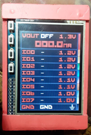
I use MATRIX 2.8 SPI TFT display from friendlyelec based on ILI9341.
Differences only in initialization display
void lcd_configure(void) {
#ifdef DISPLAY_ILI9341
you can add code from my clone of your awesome firmware.
1 Like
Thank you for checking.
I fixed the freezing problem by moving the setup to the top of the board initialization function. i think it was happening because core 1 was active.
However, it still fails to detect the PSRAM (size 0).
bus_pirate7.zip (305.3 KB)
Here is the latest test firmware. It should boot, then you can type psram and it will show the size. If detected, it should also run your test code from above.
Thank you, I will add your display init to the main firmware.
I notify you about results later.
2 Likes
Hi Ian
Yesterday I tried to find my RP2350 module for testing. But I haven’t found it yet.
![]()
I’ll continue today.
1 Like
No worries, thank youi for looking into it. I found what is not working - the QSPI module only sends 0xff, no other value.
Now I’d going to try to figure out why. Do you know the version of the PICO SDK you used?