Thanks for the feedback!
2 Likes
From Jack with dafulaielectronics.com:
"We just released this CAN bus Analyzer/Simulator.
Datasheet for simulator is link below:
http://dafulaielectronics.com/CANBUS_Simulator.pdf
Software for simulator:
http://dafulaielectronics.com/CANSimulator.zip
In your customer software to call simulator software (Integrate Simulator to your test environment), there is an example source code:
http://dafulaielectronics.com/ThirdParty_Call_CANSimulator.zip
Datasheet for .net component of this device:
http://dafulaielectronics.com/CANBUS_NET_Component.pdf
.net Component Software:
http://dafulaielectronics.com/CANCtrl.zip
Analyzer Datasheet:
http://dafulaielectronics.com/CANBUS_Analyzer.pdf
Analyzer Software:
http://dafulaielectronics.com/CANAnalyzer.zip
Please order on line if you want,
And it has 2 functions: Simulator , Analyzer.
You can choose what you want when you pay."
1 Like
Here is a simulator as well as all the file types supported by the forum. It would require some work, but I have the dev info for the software. Worth looking into. If your interested, i can zip up all the dev files next time I’m at my desk.
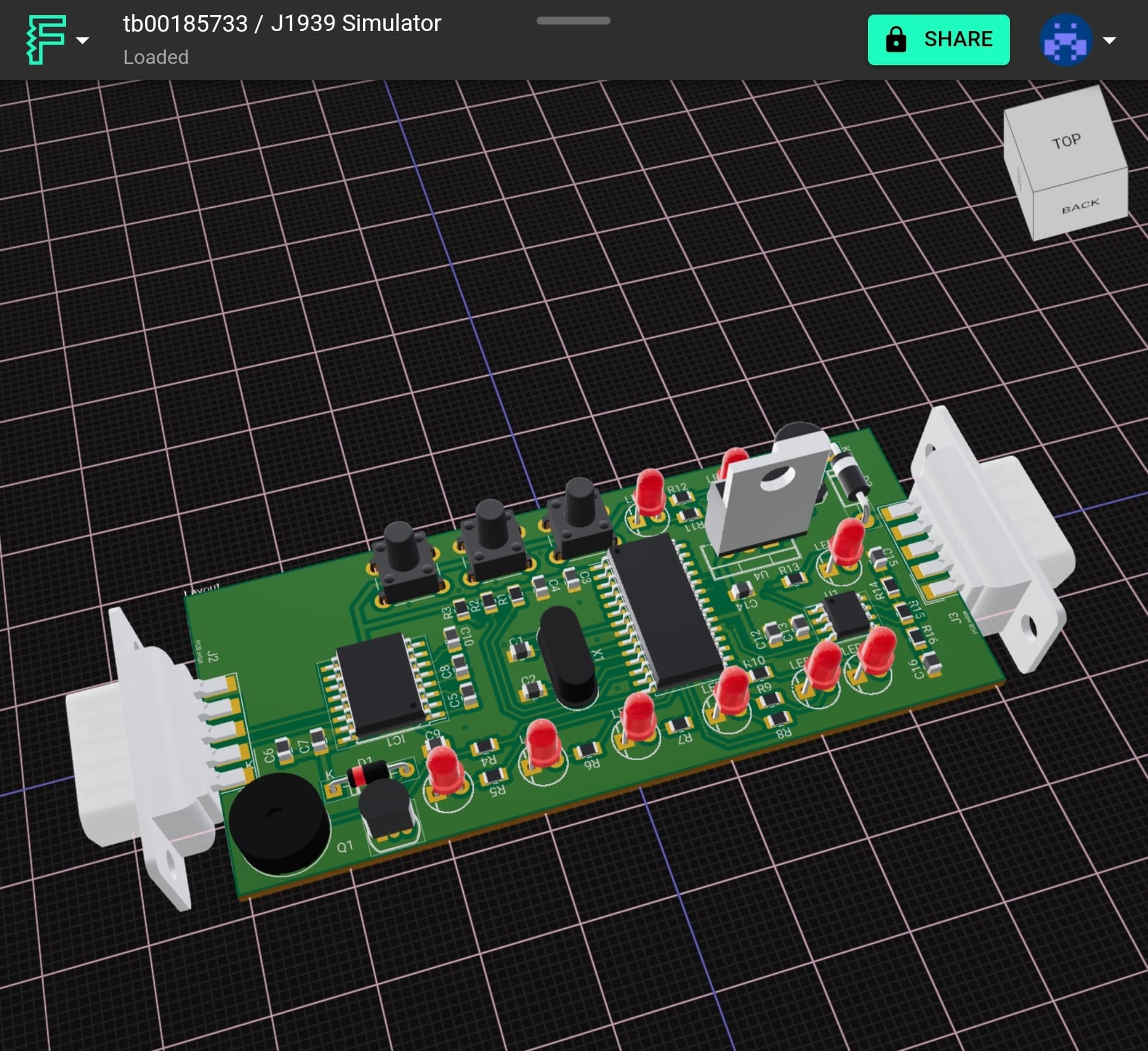
tb00185733-j1939-simulator-BOM-V2024-07-10T024555287Z.zip (20.7 KB)
tb00185733-j1939-simulator-Gerbers-Version78815411.zip (1013.0 KB)
1 Like
11.3.1.3 Interoperability of 3.3-V CAN in 5-V CAN Systems
The 3.3 V supplied SN65HVD23x family of CAN transceivers are fully compatible with 5 V CAN transceivers. The
differential output voltage is the same, the recessive common mode output bias is the same, and the receivers
have the same input specifications. The only difference is in the dominant common mode output voltage is lower
in 3.3 V CAN transceivers than with 5 V supplied transceiver (by a few hundred millivolts).To help ensure the widest interoperability possible, the SN65HVD23x family has successfully passed the
internationally recognized GIFT ICT conformance and interoperability testing for CAN transceivers which is
shown in . Electrical interoperability does not always assure interchangeability however.
Was looking at parts for this board and dug into the 3.3v/5volt thing. It seems it is only the power supply? The differential levels tend to be compatible?
- TJA1050 3.48@100
- SN65HVD230 1.95@100
If they’re mostly compatible, then I guess the TI part is the way to go due to cost, more modern design, testing, and reference design materials.
1 Like
I also recommend to add the ability to connect striped wires, because usually the connectors are custom and it is sometimes easier to just connect the wire than soldering it onto a RS232 socket.
Further more, could you please also make a plank for automotive ethernet?
modern vehicles are slowly transitioning to it instead of canbus.
Definitely screw terminals and/or wago style quick connects.
Automotive ethernet is interesting. I had a look at whats out there. It seems the cheap debug tools are USB and enumerate as a ethernet device. The RP2040 has a really slow USB peripheral, it might be a bottleneck.
1 Like
Oversimplified, but functional.
1 Like
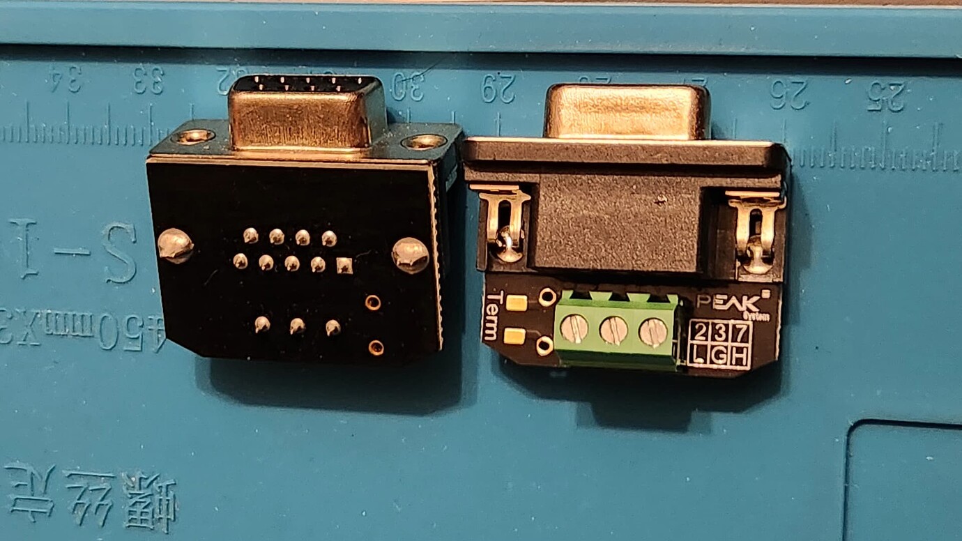
Is this wiring standard?
From my experience Vector (big vendor for automotive companies) uses different wiring on the RS232 connector
From the car hacking book that was linked to, and then reviewing CANtact docs…
The books suggests that there are two standard wirings for DB9-to-OBD-II (generally US & UK). The CANtact product referenced by the book also lists two pin mappings:
The DE9 connector of the CANtact allows for two pin mappings for different use cases:
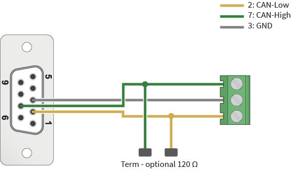
- Pins 7 (CAN high), 2 (CAN low), and 3 (ground) for standard CAN connections
- Pins 3 (CAN high), 5 (CAN low), and 1 (ground) for use with an OBD-II to DB9 cable. This is compatible with the Sparkfun OBD-II cable.
…
The final jumper is for CAN termination. Place the jumper beside the “CTE” marking to place 120 ohms across CAN high and CAN low. This is commonly used in development, when you are only interfacing with a single CAN device.
Supporting both might require some trickery.
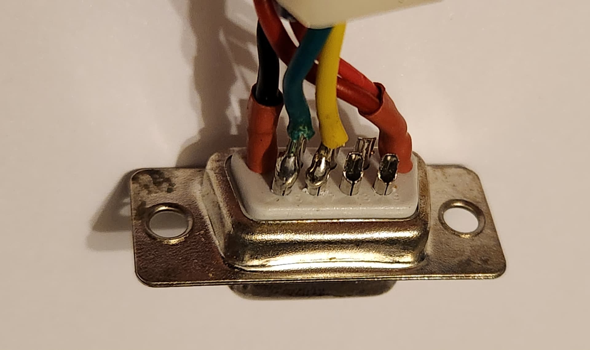
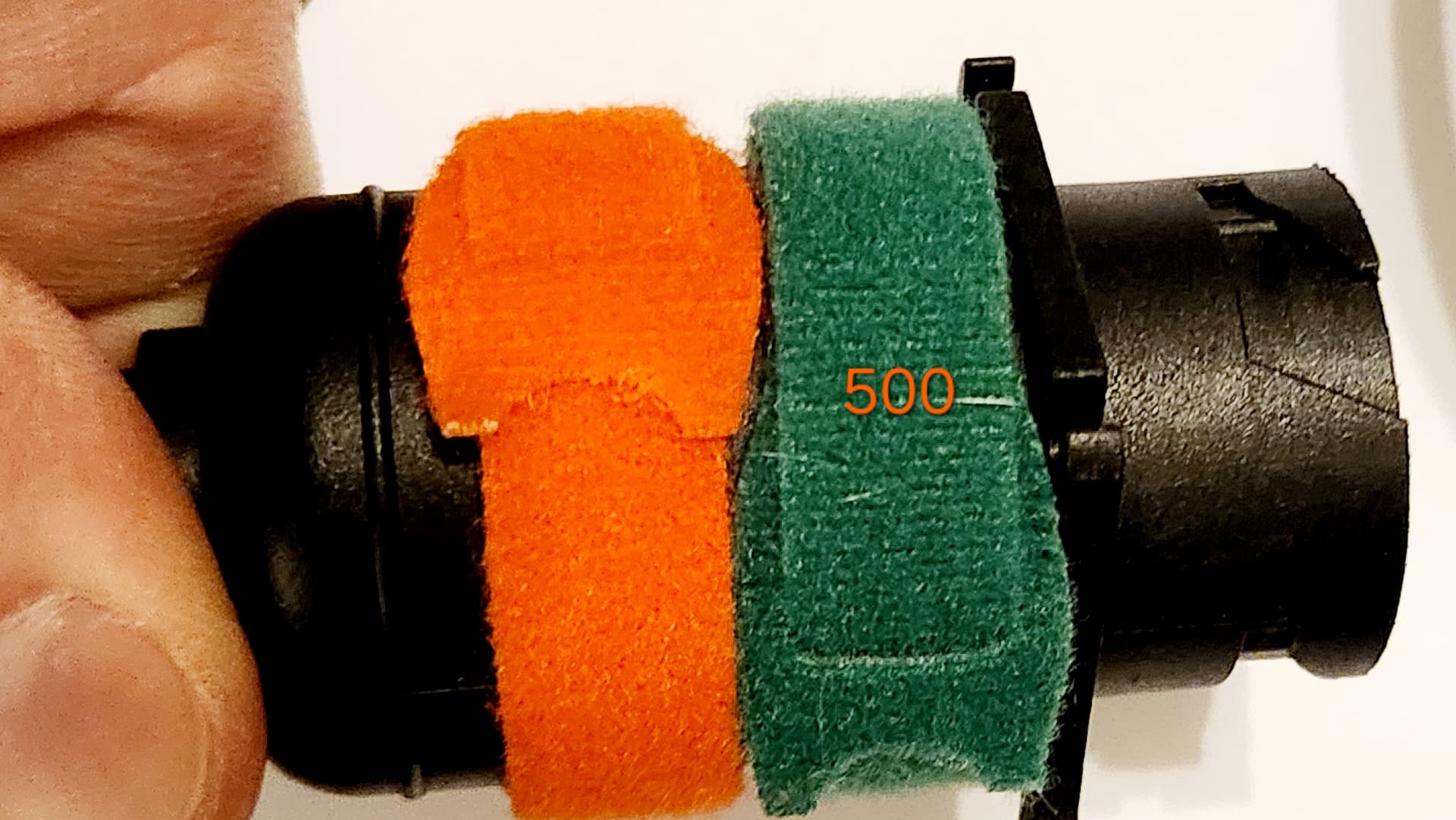
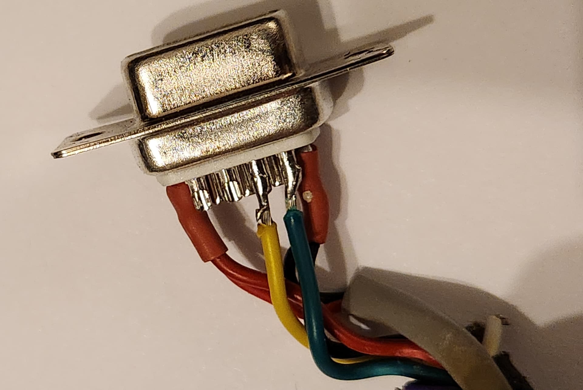
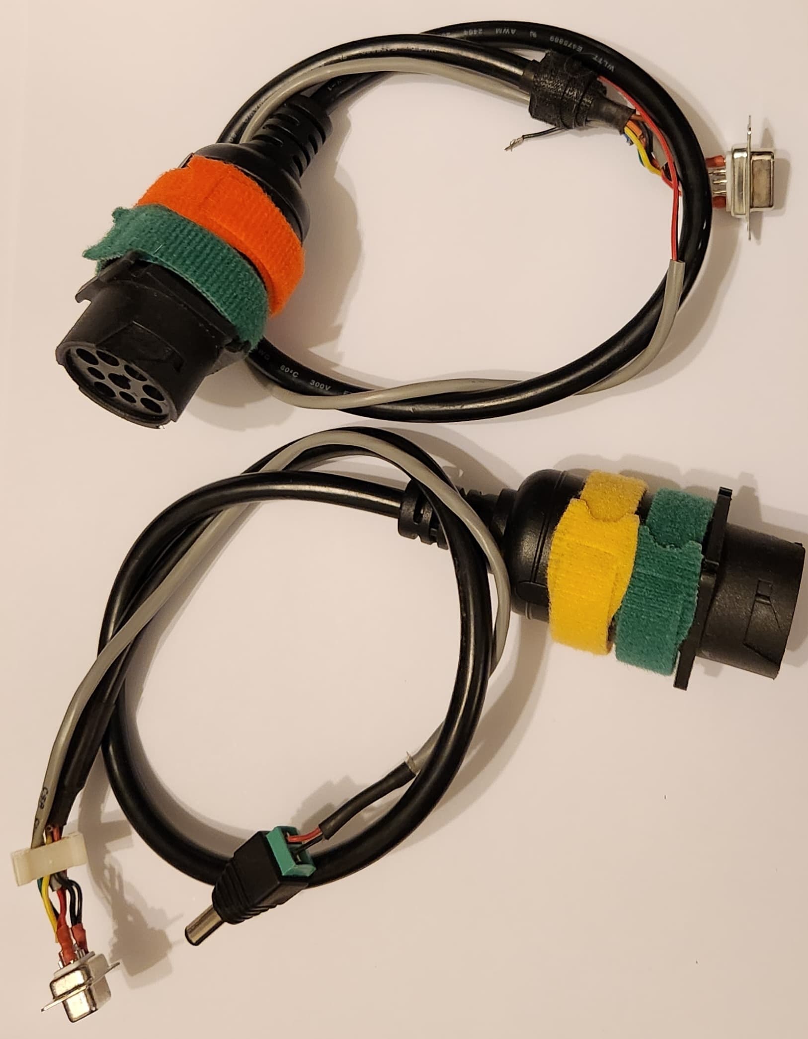
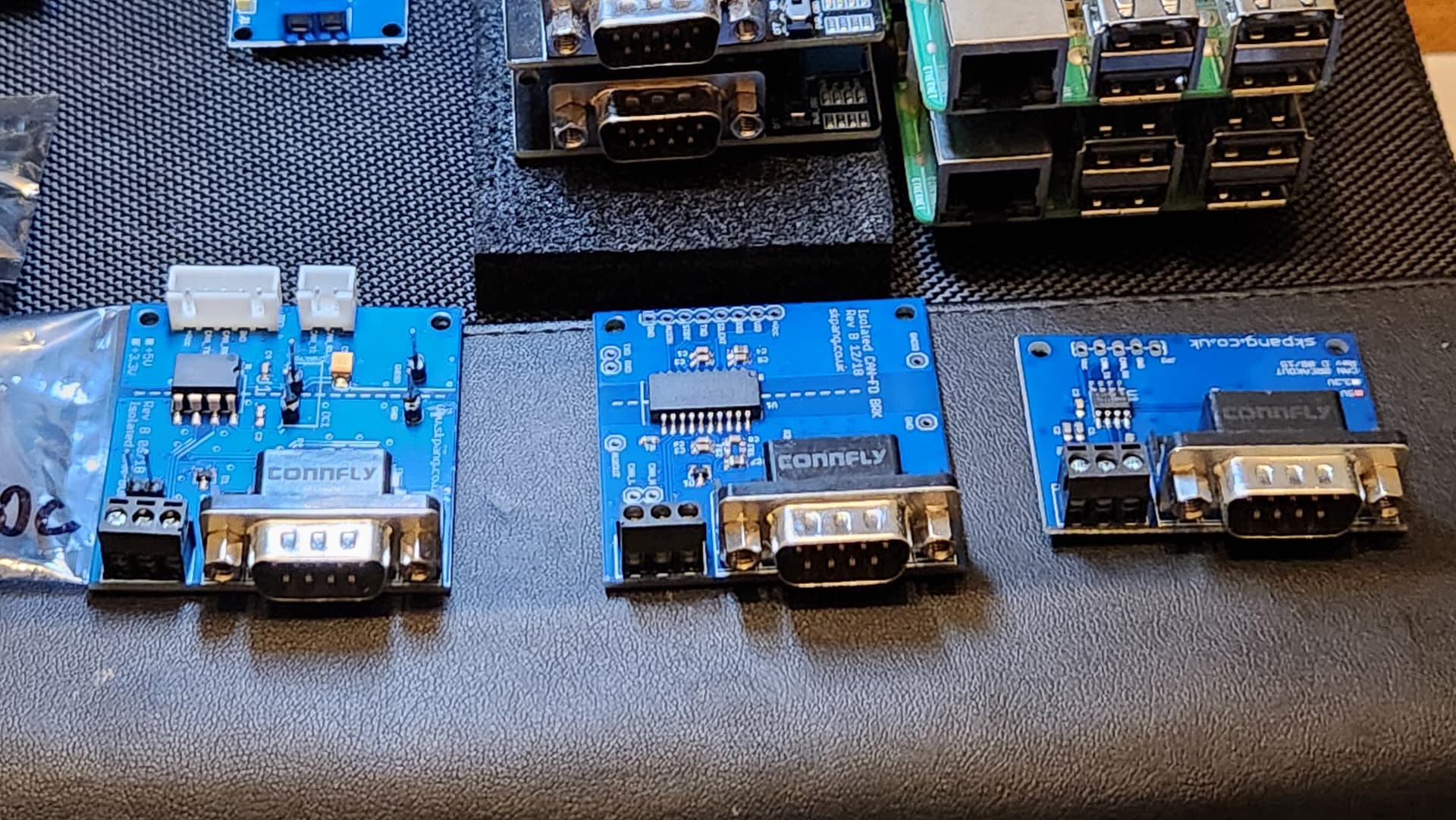
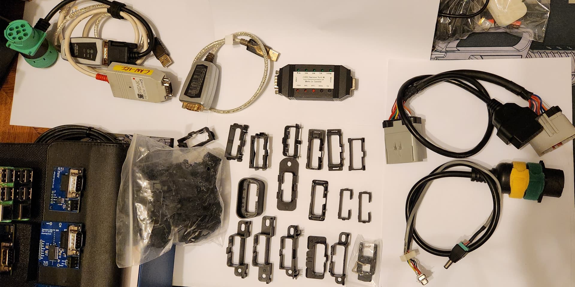
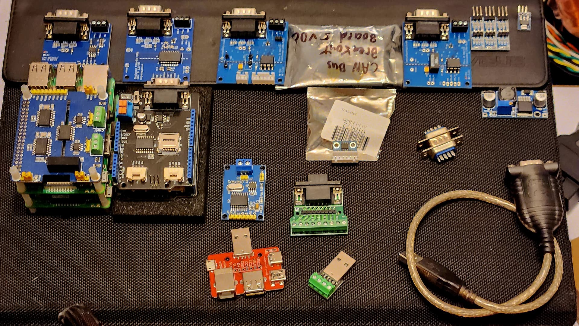
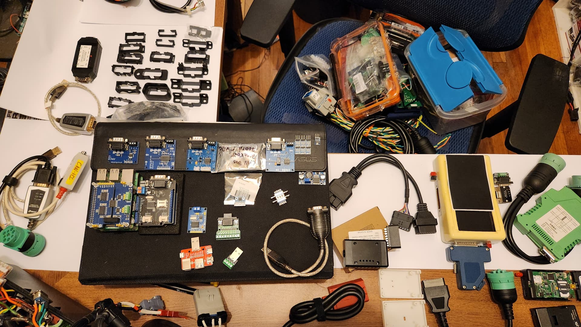
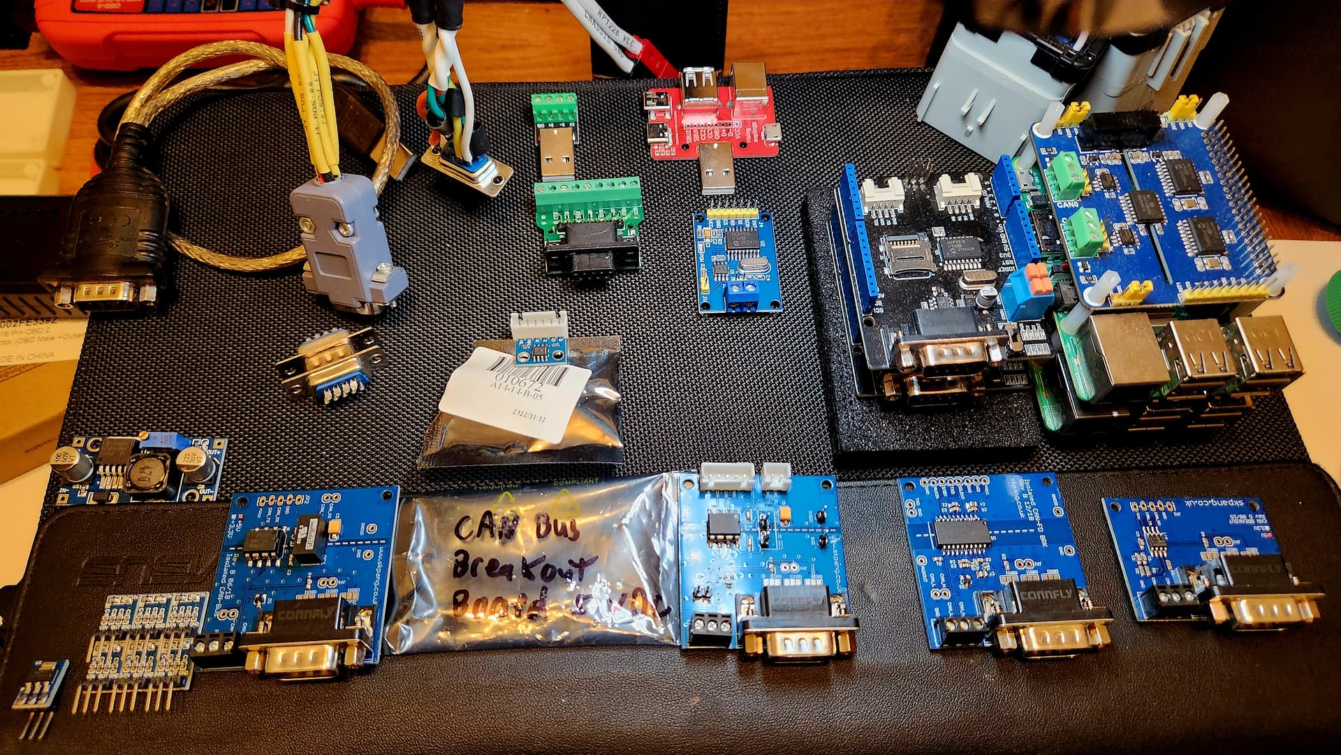
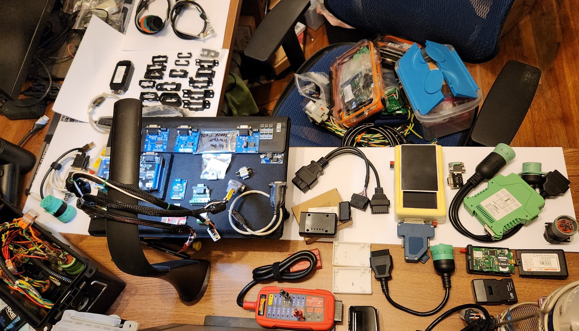
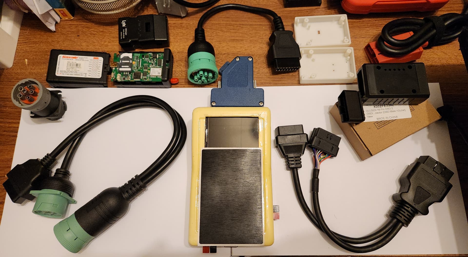
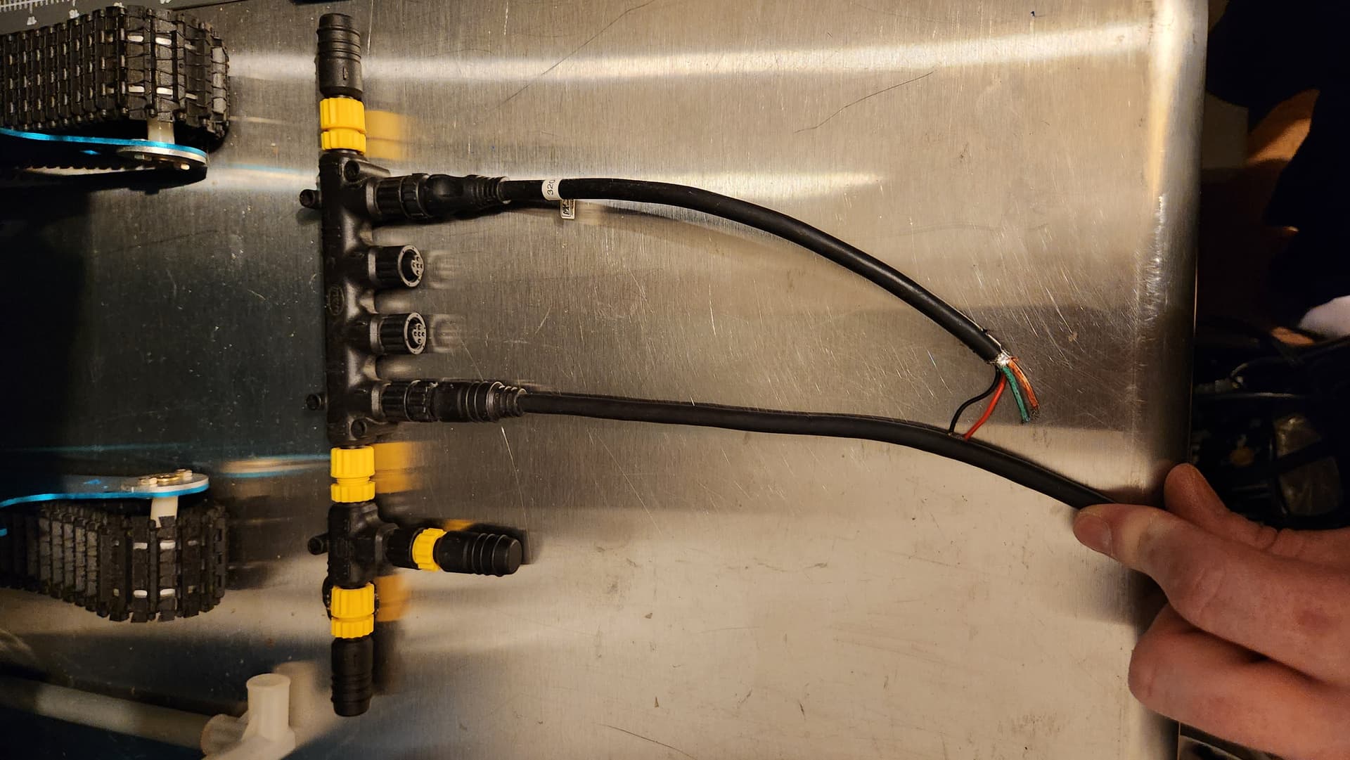
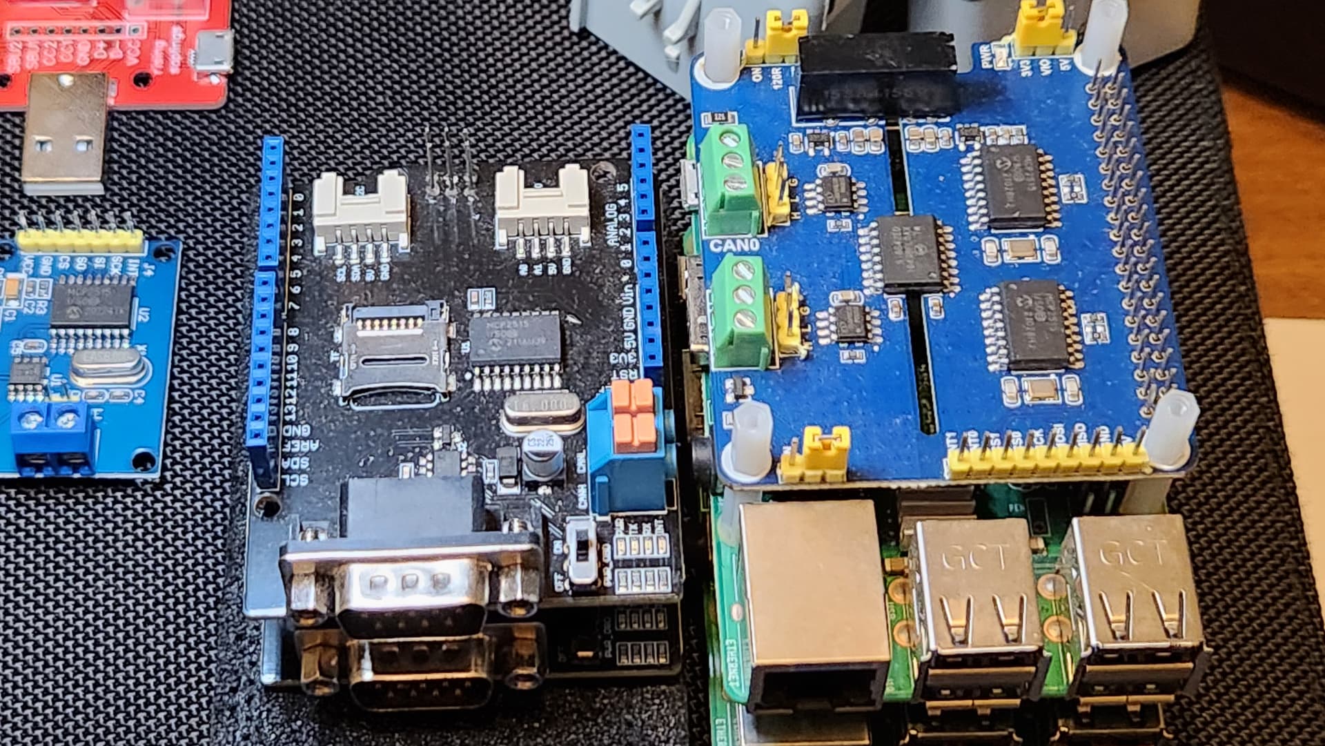
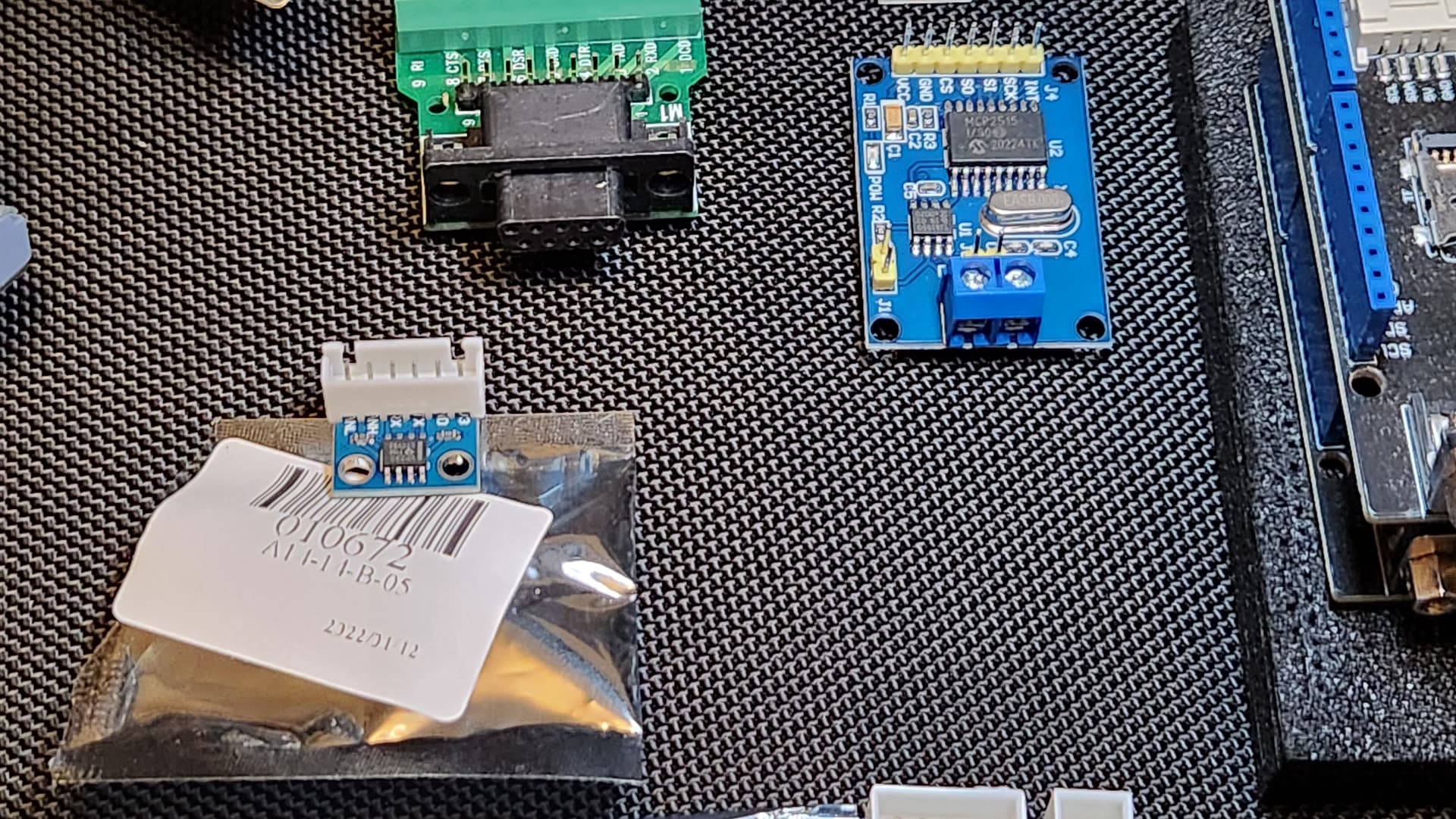
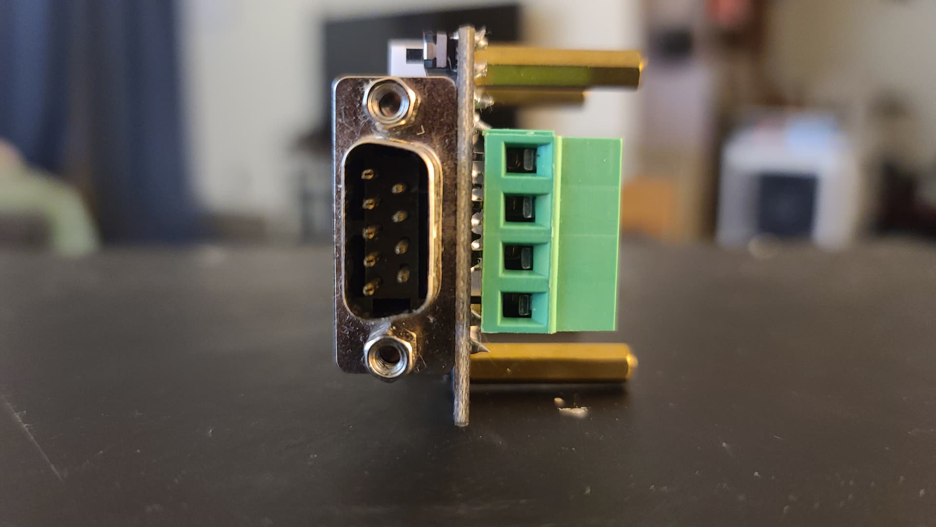
I can provide more technical details tomorrow, but here are some very basic, cost effective CAN bus development tools. I have much more, but tried to just throw the basics out tonight for a reference photos. Feel free to ask about anything you see. I also have additional drawings and documentation that will likely help simplify it. 120 Ohm terminating resistor is selectable on many of the tools. All you really need is:
Pwr
Gnd
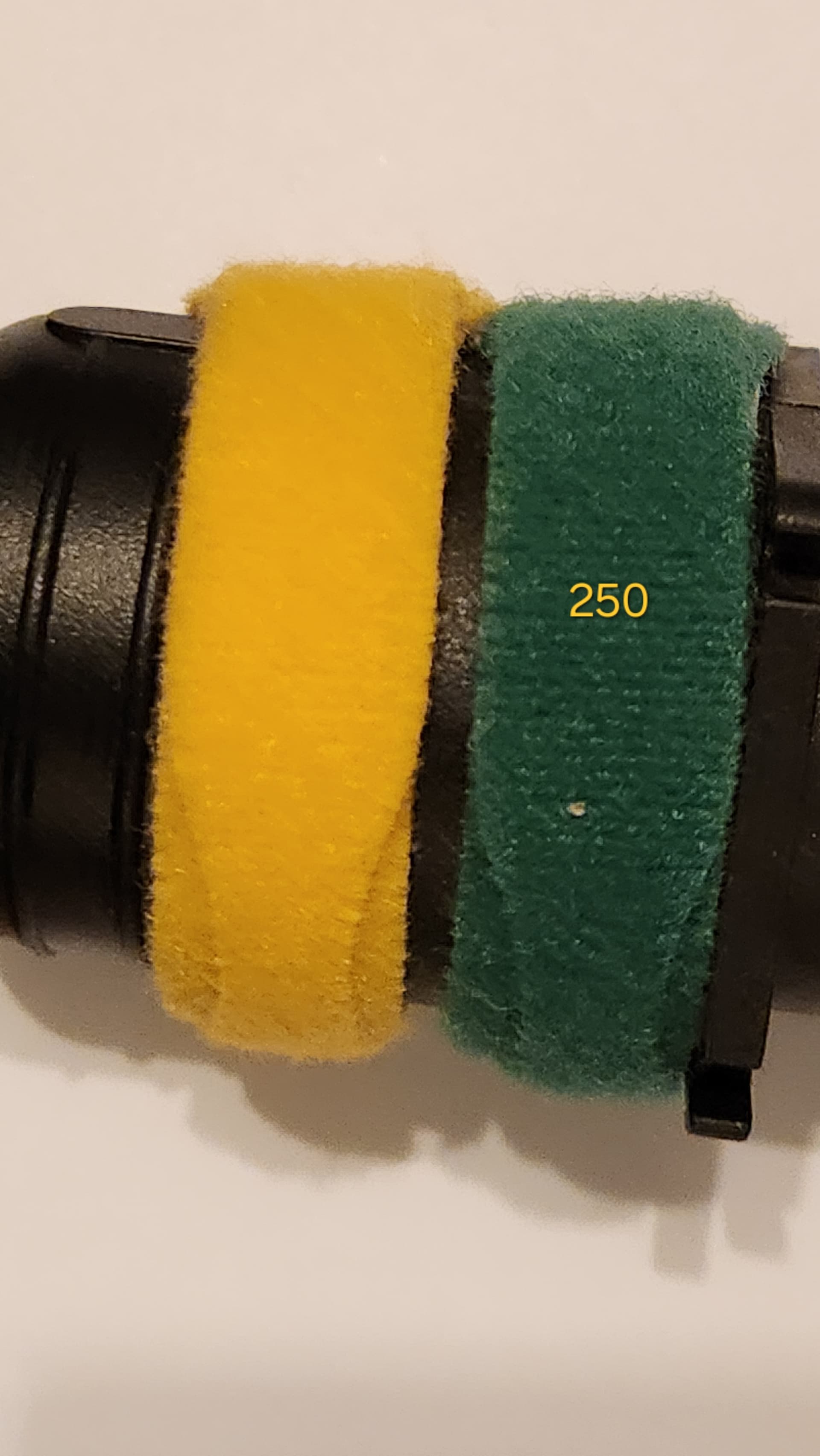
Twisted pair:
CAN H (250) Yellow
CAN L (250) Green
CAN H (500) Orange
CAN L (500) Green

3 Likes
Wow, that is quite the collection!
2 Likes
That’s mostly from the junk drawer (all functional, just inexpensive leftovers put in “inventory” for those times I need one). As you can see, it’s also mostly hobbiest board hats, accessories and custom pieces. I’ve found over the years that many are items that you need for and a project sometimes, but don’t have time/ want to wait to be held up waiting for them to arrive from an online retailer. I can’t begin to describe the amount of automotive, autonomous systems, misc. and electronics test equipment I have. I need to downsize, but would like to donate to a good cause or sell off some to cover the cost to relocate. *NOTE: This is not an effort to promote or sell anything through the forum.
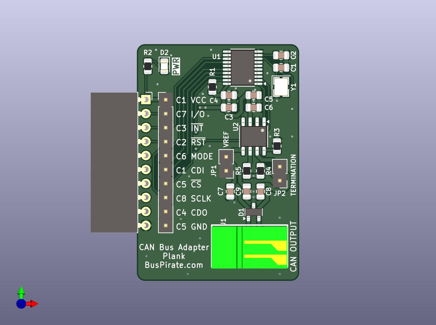
With all the RP2350 stuff this kind of fell behind. I haven’t reviewed this board yet, but it is done. When I have a chance to review I will send it off.
CAN Adapter.zip (1.8 MB)
One snag with this plank is that is has a crystal and will need to be FCC/CE tested.
4 Likes
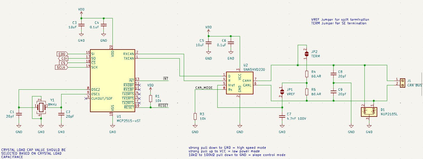
Probably R3 should be a jumper.
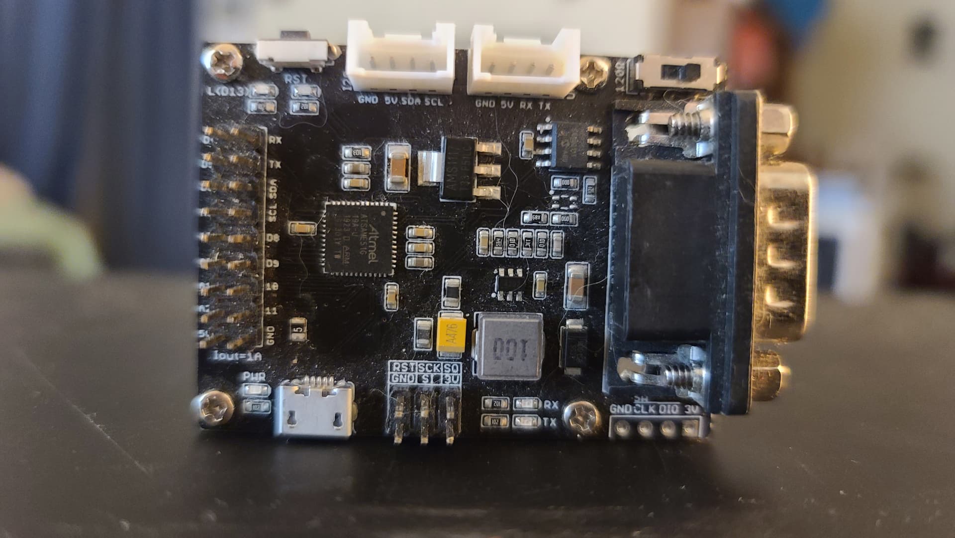
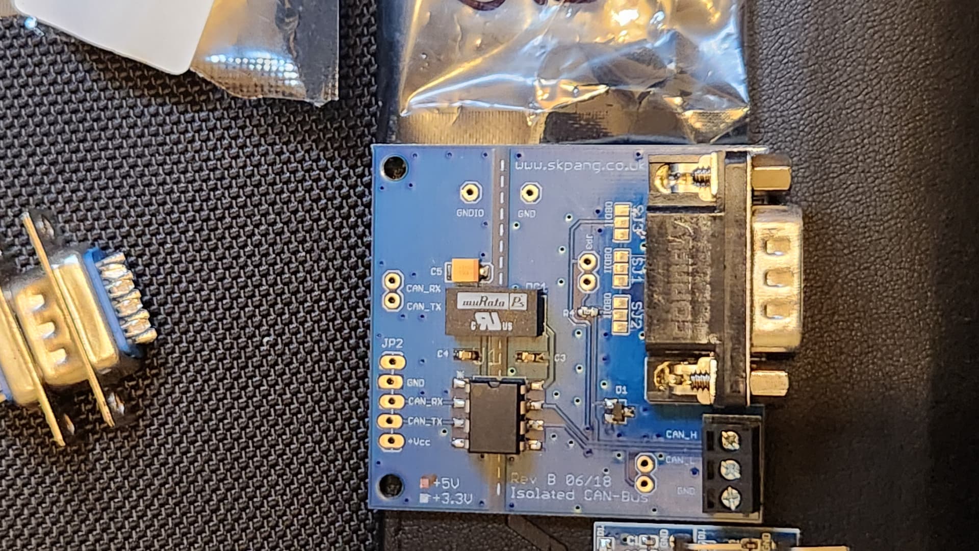
I had to dig this out of storage. I’m interested in testing/buying a CANbus/OBDII plank for the BP. The more I can consolidate, the better. I apologize for the poor picture quality; I was in a rush and didn’t have time to clean the board.
Will you be adding holes for feet?
Jumpers are easy to lose. Is it cost prohibitive to use smt dip switches?
Is there any indicator for can hi/ can low? Both labels, such as on the silk screen, as well as activity indicators for either?
Yeah, canh/canl silkscreen labels, smd switches and holes for standoffs would be nice.
If you are considering smd switches, you might also add one for the speed control thing of the transceiver. one position for hard gnd for high speed and one with a little more resistance, like 22k or so, for a slower slope in case of EMI issues on the can bus. the 10k you have there now would otherwise have to be desoldered and replaced with a resistor matching the speed of your bus. i think a switch between two common speed levels would be enough for most applications.
1 Like
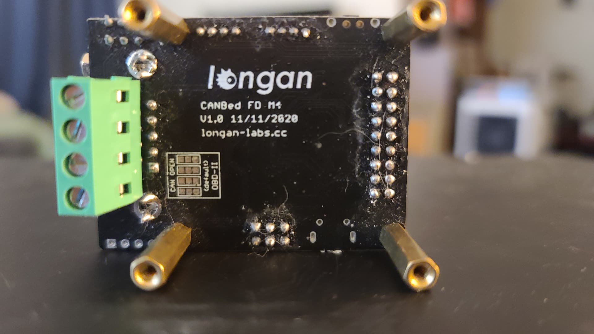
I went through a ton of CAN modules on a project two years ago which used CAN FD on an industrial machine (they were for motor control). If your CAN controlled widget uses FD, your choices are limited. If you use speeds above 1 Mb, restricted even more. There were a couple of modules that used the RP2040, but my memory is vague. I’ll dig into that drawer today and report back.
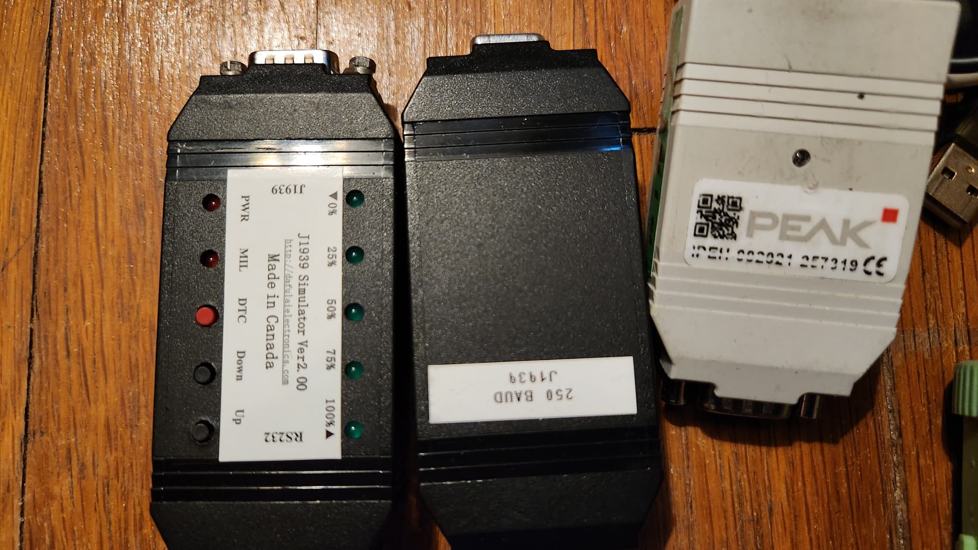
I also had one of those Peak RS-232 to CAN modules pictured above, installed in my system which the main controller MCU use to drive the motors. I would use a USB-connected CAN module to monitor the bus for telemetry and configuration.
There exists a reasonably standard and well adopted serial protocol for talking to these adaptors. Not sure if that would be helpful to use in a Bus Pirate or not. I used them manually a few times, but primarily I generated them programmatically
-Chris
2 Likes