Beware those DE-9 to screw terminal adaptor boards. I have an assortment from Ali Express and one of the genders is labeled wrong on the silkscreen. It’s like they use the same tiny PCB for both the make and female connector. You can’t do that because the pin number will be backwards
Actually, you could use the same PCB itself, it’s just that the silkscreen legends would be different.
However, this is a forum for Dangerous Prototypers, so such caution is probably unnecessary if not unwanted. A few sparks when you short your CAN 5V power supply to ground, fry two logic analyzer inputs, blow out a CAN bus transceiver, and set fire to your engineering notebook — all before 9am — is probably just par for the course with this crowd.
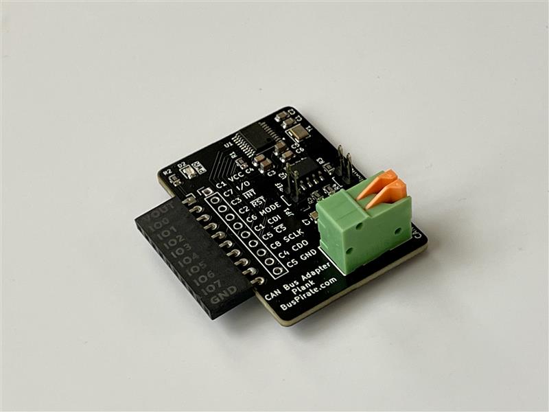
We’re going to have a small batch of these hand assembled. I’m not sure what to do with it besides send them to you all as samples, but it’s time to have a prototype.
Just to follow up before I send these off to have a few made. Anything known at this point that should be addressed in advance? I’m hoping to add these to the queue in the next few weeks.
I checked and it’s not listed on the DirtyPCB site, so I presume this is a small-sample to see if firmware will be written.
I’ve wanted to sniff my cars’ CAN bus for years, and there’ve always been roadblocks. That said, I have zero experience and less time to learn this area.
Accordingly, I would not be contributing to the actual development. As a result, any and everyone else should have higher priority. If you then still have leftovers and want to reduce clutter, … send one my way!
Count me in too! Could be useful for my new 3d printer. I’m in the same boat as Henry, I don’t know how much I could help. I’d be willing to pay for it though.
thats why i havent replied. I do plan on getting back into hardware hacking stuff, but ive been down an audio circuitry/synth rabbit hole. If i get one it will probably sit for some months.
Has anyone showed interest in actually working on the fw?
I just looked at the BOM, and reading raw bytes should be easy
It is using:
MCP2515-xST
SN65HVD230
This means it uses SPI interface for the MCP2515 which has its own command set of 1-byte instructions:
Im pretty sure we could send simple commands with the existing SPI mode and then READ RX BUFFER.
–
EDIT:
so the gameplan for a CanBUS specific mode would be:
1.) Auto reset/init
2.) configure baud rate
3.) filters?
4.) Parse incoming Can frames to more human readable like CAN ID, Data length, DATA
maybe someone could add a replay feature in the future. and of course we’d want to be able to load .dbc files in the future for translation.
we could get ideas from GitHub - cantools/cantools: CAN bus tools.
i got it working with a basic OBD-II bluetooth module. so if that is able to receive and interpret data from it, so im sure we could see something on the buspirate (as far as raw data)
I think we could wire up on an actual car without too much worry as well.