I NEED this new rev when it comes out. ![]()
2 Likes
I like the idea of breakout pin headers.
How would that look like in detail?
Version 1: one single row of 9 pin headers on each of the two DB-9 connectors.
This could be used like this:
- The device you want to connect to uses some other kind of connector than DB-9 and you want to connect a breakout cable to that connector. Hooking up pin headers is easier than making a custom DB-9 adapter
- You need to supply static signals for things like DSR, DCD, RI for example in a null-modem style connection. You now use jumper wires to connect for example DCD, DSR and DTR together to make device detection work.
- You need fully software controllable signals for DCD, DSR, DTR, RI, for example because they are (mis-)used to implement some reset/bootloader logic. You now use the second RS232 interface on the plank to control these signals by connecting for example TX of the second RS232 interface to DTR of the first with a jumper wire
- If the device you want to connect to uses a non-standard DB-9 pinout you are out of luck and need an additional breakout adapter/cable
Version 2: dual row 9 pin headers and 9 jumpers on each of the two DB-9 connectors
- By default all 9 jumpers are set, bridging the RS232 interface and DB-9 connector in the default pinout
- If you encounter a non-default pinout you remove the jumpers and can then manually reroute the pinout with jumper wires
I’m not sure how often non-default pinouts are in practice and if it is worth the extra space, solder joints and parts for version 2.
Another idea: I have often seen that manufacturers are running RS232 over RJ45. The most common example of this is the Cisco-style pinout that is very common on professional network equipment like switches, routers, PBXes,… You could add 2 RJ45 sockets with the Cisco-pinout to the plank for this, wired in parallel to the two DB-9 connectors.
But with RJ45 I have seen different pinouts than Cisco-style too. The most famous is probably older APC UPSes that had several different pinouts and they sold various totally overpriced adapters for them. But I remember updating a PBX with a hand-made RJ45-RS232 adapter cable one time. So for RJ45 the version 2 with jumpers and fully reconfigurable pinout would make more sense.
@ian now you get to decide where useful features end and feature-creep begins…
3 Likes
One more thing to consider when doing a redesign:
When the new case will have sticky feet it will be higher. So the height of the standoffs will probably have to be adapted.
3 Likes
Good point. I noted this a few days ago and we’ll be working through it.
This also applies to the test/programming rig that’s simmering on my workbench. I’ll need to relocate the carrier pogos and cut holes in the acrylic so the feet just fall through.
2 Likes
Received this via email. Anyone have thoughts? I’m open to being wrong, but I did a bit of research going onto this plank and found that while RS232 in general is messy, I tried to use the most common pinouts and plugs.
1 Like
[quote]I agree with your comment in the posting. It is messy. Very messy. I suspect I am much older than you, and in my lifetime, the situation has never improved. They still call the 9 pin DB-9 instead of DE-9. The second letter is the connector SHELL size.
The two big confusing implementations are the use of TX, RX pin names in DCE. Those refer to the network side function, not the pin function. Implement a DTE to DCE hookup and it is a Tx pin to Tx pin. The second is when they went from DB25 to DE9. The Tx and Rx pins got swapped! Why? Who knows. When someone sees a BD25 to DE9 adapter they will see a Tx-Rx swap, and assume it is a NULL adapter, but they would be wrong. It is simply rearranging the pins per the proper pin assignment for that size connector.
Let me give you another example. I am looking at a bus tester. 25 pins. One side is labeled DTE and the other DCE. Both sides are female sockets. Yet, a later implementation of the same model, has female sockets for the DTE side, and male pins for the DCE side. This is correct. Straight through implementation is male to female. A DCE is female and would connect via a straight cable (M-F) to the male pins on the tester. Same for the DTE side.
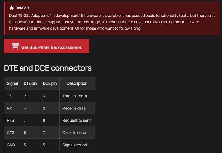
In any case, you should include those Advantech links. That company has many diagrams and information that was very helpful to me in figuring what is what. Also let them know that that “danger” image with pin numbers is the “wrong” example. Otherwise, someone will see a contradiction between that image and the images below it (I should have done that, but I figured you would recognize your own web page).
If I could be of more help, let me know. Good luck with your project!
[/quote]
Follow up.
I am not an expert in serial; I still call it a DB-9 port. I would defer to someone who is an expert.
EDIT: after additional review, I did not find any problems with the silkscreen / port types
If I summarize correctly, “Engineer” identified two issues:
- that genders on the boards’s ports are backwards (or the labels are backwards)?
- that pins are incorrect?
I can only comment for now on #1:
YES, there appears to be a mismatch between the labels and port genders.
On actual equipment, male at the source (DTE) and female at the equipment (DCE) are the common case. Let’s presume the goal is the ability to use two normal / passthrough serial cables to man-in-the-middle (or a single cable to connect as either terminal / equipment).
On the plank …
- … the port labeled as “to equipment” …
- … would act “as if” the plank was the terminal
- … and thus should be the same as typically seen on a terminal (computer)
- … and thus should be a Male DB-9 port
- … and be labeled as “DTE”
- … the port labeled as “to terminal” …
- … would act “as if” the plank was the equipment
- … and thus should be the same as typically seen on equipment
- … and thus should be a Female DB-9 port
- … and be labeled as “DCE”
Simplest Fix?
If we simply reverse the labels of “<-Equipment” and "Terminal → " on the PCB, would that resolve the port gender mismatch vs. DTE/DCE vs. label disparity?
EDIT: The meaning of the Equipment and Terminal labels are potentially confusing. If a goal is to be a “Man-in-the-Middle”, the labels might be incorrectly read to mean that one should attach the equipment to the DCE port, and should attach the equipment to the DTE port. It also might correctly be read to mean that the DTE port is “acting as” a terminal, and the DCE port is “acting as” communications equipment… in which case the labels are redundant to the DTE and DCE labels.
I’m start to remember why I hate working with COM ports… but I am now correcting that there is nothing technically wrong with the silkscreen labels.
2 Likes
Next step… digging into naming conventions. This is critical to the discussion, as it’s even more obtuse than USB data directions.
TLDR; All signal names on a COM port require viewing the signals from the viewpoint of the terminal (DTE) port (e.g., a computer).
Poor naming conventions make it easy to make mistakes
USB device data transfer direction is a great example of choices that make it easy to get confused. When working on a USB device firmware, any reference to IN means your firmware is sending data, and any reference to OUT means your firmware is receiving data. This is because the data transmission must always be referred to from the point of view of the USB host (or at least upstream device). As a result, there’s increased cognitive load when mere mortals try to understand USB device firmware code. It doable, just adds a constant mental pressure.
Well, it turns out that USB adopted this poor practice from COM ports. The naming of pins and signals here also requires constantly being aware of whether the port is being used as a terminal (DTE) or equipment (DCE) port.
Of course, COM ports didn’t just apply this to the Rx and Tx signals, they also applied this to the DTR, DSR, RTS, and CTS signals … all of which also be viewed from the DTE point of view.
It’s a mess … and further increases cognitive load. That’s the exact opposite thing one would want for naming of signals, but it’s what we have to work with. As a result, it means it’s really easy to get stuff wrong. Perhaps this is why some of the not-quite-serial products exist in the world … not corporate greed, so much as undetected confusion by designers (until too late in product cycle).
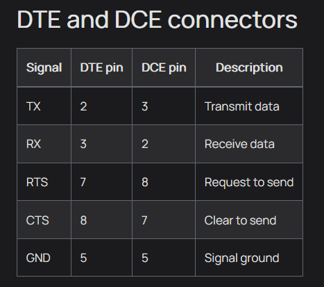
For today’s step in reviewing this, I was able to verify that a standard COM connection would have the following characteristics:
DTE == Male port (e.g., computer side)
DCE == Female port (e.g., comms equipment side)
| Pin | Direction | Signal | Notes |
|---|---|---|---|
| 1 | DTE ← DCE |
DCD |
Data Carrier Detect |
| 2 | DTE ← DCE |
Rx |
Terminal receives from Comms Equip |
| 3 | DTE → DCE |
Tx |
Terminal sends towards Comms Equip |
| 4 | DTE → DCE |
DTR |
Data Terminal Ready |
| 5 | ---- n/a ---- | GND |
Signal ground |
| 6 | DTE ← DCE |
DSR |
Data Set Ready (should have been DCR?) |
| 7 | DTE → DCE |
RTS |
Request To Send |
| 8 | DTE ← DCE |
CTS |
Clear To Send |
| 9 | DTE ← DCE |
RI |
Ring Indicator |
Next, what does the plank do?
2 Likes
My prior few posts confirmed:
DTE == Male port, Data Terminal Equipment (e.g., computer)
DCE == Female port, Data Communications Equipment (e.g., router, modem, etc.)
… and that all signal names must be considered as being from the viewpoint of the terminal (DTE).
- The plank labels the male port as
DTE, and labels the female port asDCE. So far, so good … labels and ports types match… - The plank labels the male
DTEport asTerminal ->, and labels the female portDCEport as<-Equipment. While redundant, this is fine.
Plank Pin Assignments.
![]() This might all just be a matter of naming … the buspirate documentation might be naming signals differently than how folks who deal with COM ports on a regular basis name the signals. Specifically, maybe the signal names in the buspirate docs are not “as viewed from the DTE port”?
This might all just be a matter of naming … the buspirate documentation might be naming signals differently than how folks who deal with COM ports on a regular basis name the signals. Specifically, maybe the signal names in the buspirate docs are not “as viewed from the DTE port”? ![]()
But, let’s presume that the listing of pin connectivity is from the DTE point of view. Here’s what I would expect the connections to look like:
| Signal | Port | PortPin | Expected MAX232 |
|---|---|---|---|
Tx |
DTE |
3 | RS-232 Output (data from BP) |
Tx |
DCE |
3 | RS-232 Input (data to BP) |
Rx |
DTE |
2 | RS-232 Input (data to BP) |
Rx |
DCE |
2 | RS-232 Output (data from BP) |
RTS |
DTE |
7 | RS-232 Output (data from BP) |
RTS |
DCE |
7 | RS-232 Input (data to BP) |
CTS |
DTE |
8 | RS-232 Input (data to BP) |
CTS |
DCE |
8 | RS-232 Output (data from BP) |
@Ian – Can you confirm the schematic connects the above DB-9 pins to the corresponding pins on the MAX232 chips?
If accepting the website list of pin connections, it would appear that:
Tx/Rxswapped onDTEportRTS/CTSswapped onDCEport
@Ian – Was it helpful for me to write up my thought process in reviewing this, or was that too “noisy”?
TLDR:
There is a possibility that the current boards may not be usable for straight-through connections with standard-pinned equipment. If so, the anonymous engineer deserves great thanks for raising awareness on this (relatively) early.
3 Likes
Thank you so much for lending your eye for detail to this issue, I greatly appreciate it. Far from noise. I don’t have the capacity to investigate properly right before spring festival hits (18 more days). There are only around 20 of these out there, mostly among forum regulars, with no complaints thus far. If we find an issue I will of course replace all the boards.
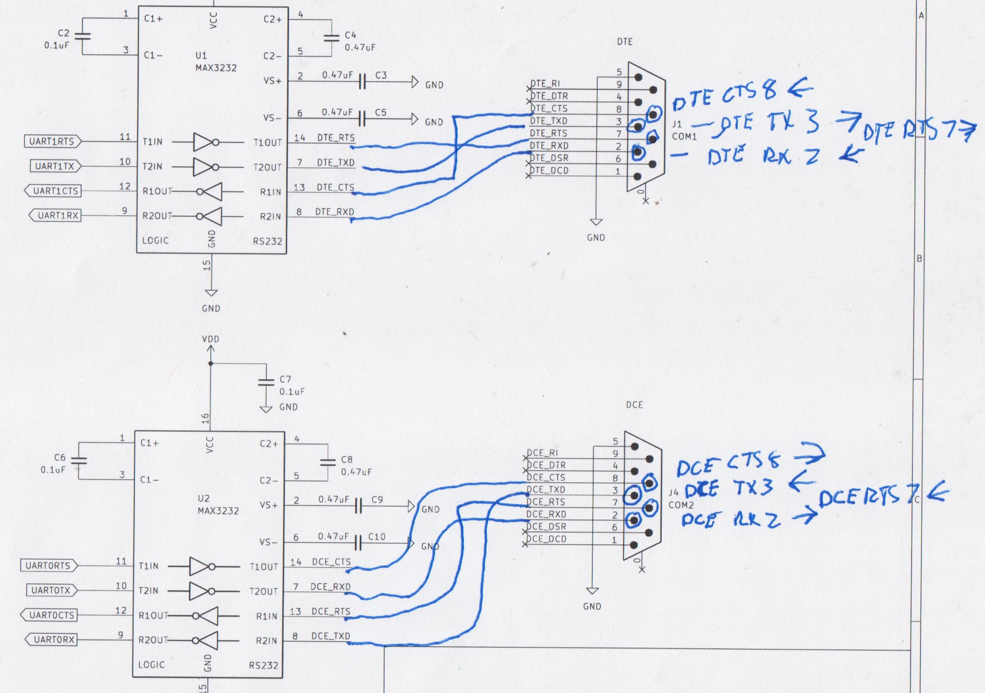
In your table above I assume the last entry is DCE (DTE is repeated twice). The schematic connections are consistent with your table.
I think there may be two sources of confusion. One is that the schematic is opinionated from one side, eg “as viewed from the DTE port”. DCE_RXD for example is an OUTPUT from DCE to DTE. So the schematic is named from the DTE point of view. However if you look at the direction of the buffers and the connection on the Bus Pirate side the connections are going the right way.
The test for this is the actual production test of the board. We connect a straight through cable to both ports and run the test command in UART mode. The test does data both directions, as well as accumulating data in the FIFO buffer until the CTS/RTS signals are needed.
In the documentation there is this table, which is not opinionated. The signals are named from the point of view of each port instead of as viewed from DTE. I did this because it makes the most sense to me, though I am indeed not a veteran of the serial port format wars. Could my table be the source of confusion?
2 Likes
Ian and others,
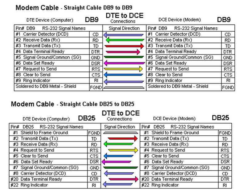
The table is incorrect. There should be no opinion here. There are only statements and supporting references. RS-232 is a standard to be followed not flavored with one’s personal understanding. I am not trying to be harsh here, just trying to emphasize the need for correctness. You are not a user of RS-232, you are the test equipment manufacturer, and thus set the standard for others that connect to your equipment. In your table, Pin 2&3 are swapped on the DTE. DTE to DCE the pin numbers and names must match. As DCE devices are most often PSTN modems and bus converters (RS-232 to RS422), the “TX” is from the point of view of the network. Tx is the data to be transmitted over the network away from you. Please look at the colorful graphic I provided in the info you posted for me. I recommend you add the preposition “TO” to DTE and DCE, then there is no confusion on who’s point of view.
Regarding DB vs DE. DE-9 is the CORRECT nomenclature. Repeating it over and over will not make DB-9 correct. When DE-9 were introduced, it was assumed by someone that the pin numbers were simply changed from 25 to 9. Once the barn door opened… The second letter is shell size, and that small shell size is “E”. The VGA connector is 15 pins, do you call that a DB-15? No, because there are two 15 pin connectors, the one in the “E” shell (VGA), and the one in the original “A” shell. Sometimes the VGA connector is incorrectly referred to a HD-15. Please checkout Wikipedia. As engineers of test equipment, you have a higher responsibility to get it right, and not succumb to popularism.
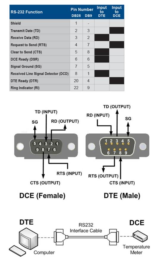
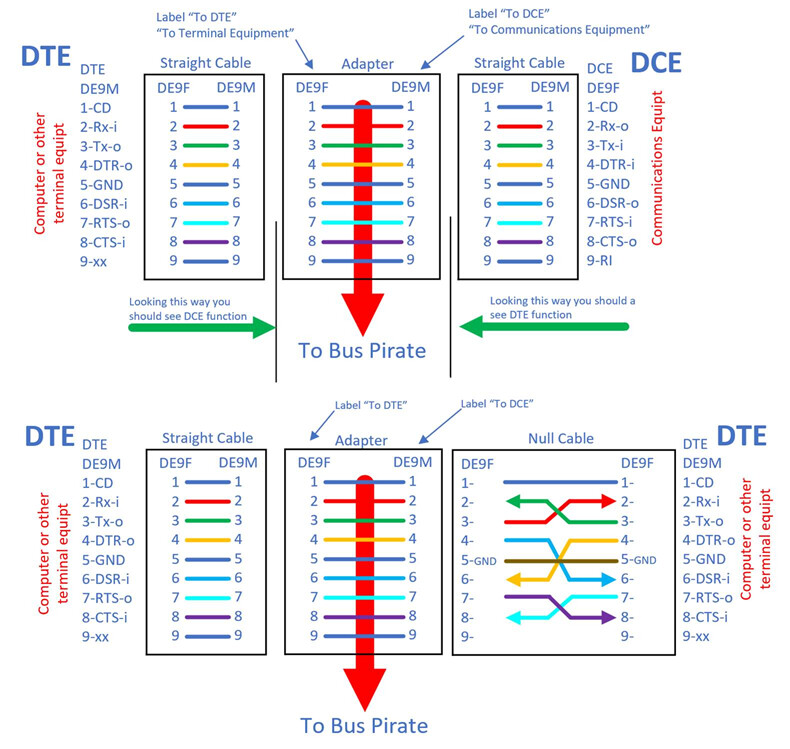
This graphic is my interpretation of your “adapter” as it sits in the system.
4 Likes
Henrygab,
Sorry if I don’t get the quote function right…
- The plank labels the male port as
DTE, and labels the female port asDCE. So far, so good … labels and ports types match…
this where it is backwards. The DTE SIDE of the adapter should be female sockets and label “TO DTE”. Then a straight thru cable can be used. Same for the other side, “TO DCE” and male pins.
- The plank labels the male
DTEport asTerminal ->, and labels the female portDCEport as<-Equipment. While redundant, this is fine.
*Both sides are “equipment”. If you want to keep it short use “COMMS” & “TERMINAL”, or nothing, and use “TO DTE” and “TO DCE” * What is BP?
Your port pin naming convention in your table is correct, but may I suggest the point of view should be a system point of view, i.e. the terminal and modem and network are a system, and TX data is transmitted data from your keyboard/terminal to the network away from you. Like a 2-way radio. Push the button and the signal is transmitted away from you. A systems point of view may help resolving some of these “point of view” questions. I think this is the origin of the original Tx=Tx, output on one side and input on the other with the same names.
I also noticed the schematic shows transceivers between the DTE and DCE ports. Any anomalies on the bus, e.g. intermittent behavior on the system you are trouble shooting, could be masked or “repaired” by the transceivers, by restoring defective or weak signal levels. Am I missing part of the schematic or is this the intent?
I ripped my hair out of my head getting some of this squared away in my head. I have equipment from leading manufacturers that violate some of the specs, as all DTE are male pins and all DCE are female sockets, even calling computers DCE. Persevere, and don’t capitulate. Once you get it right you know you will have done the right thing.
Good luck.
Bob
4 Likes
My table error – Fixed!
Yes, fixed!
Schematic named from DTE POV – Good!
Good … that is how it should / must be. (Imagine the confusion if you started referring USB IN endpoints in the buspirate firmware as OUT endpoints, because it makes more sense from the firmware point of view!)
Website Table – Confusion Central!
Yes, this is a source of confusion! The statement, “because it makes the most sense to me” may be seen to contradict the statment “which is not opinionated”. ![]()
More importantly, to avoid actually being opinionated, the signals must remain named in all cases as viewed from DTE.
Strong recommendation: Update the table on the website to reflect signals names in accordance with the standard.
Schematic Pins – Good!
The schematic appears to show standard pin connections for the ports, presuming that DTE is the male port and DCE is the female port.
Schematic Labels – Ouch!
If there was only one DTE port, then the labels in the schematic would be fine for DTE side. The labels in the schematic for the DCE side, from the MAX3232 chip to the buspirate, are also wrong, and therefore may lead to confusion when folks try to follow the schematic.
Recommended schematic label updates, in order from top to bottom of the schematic posted:
| Old Label | Rename to | Verbose Rename |
|---|---|---|
UART1RTS |
UART1_DTE_RTS |
UART1_DTE_OUTPUT_RTS |
UART1TX |
UART1_DTE_TX |
UART1_DTE_OUTPUT_TX |
UART1CTS |
UART1_DTE_CTS |
UART1_DTE_INPUT_CTS |
UART1RX |
UART_DTE_RX |
UART_DTE_INPUT_RX |
UART0RTS |
UART0_DCE_CTS |
UART0_DCE_OUTPUT_CTS |
UART0TX |
UART0_DCE_RX |
UART0_DCE_OUTPUT_RX |
UART0CTS |
UART0_DCE_RTS |
UART0_DCE_INPUT_RTS |
UART0RX |
UART0_DCE_TX |
UART0_DCE_INPUT_TX |
DB-9 vs. DE-9
@Bob11746 is technically correct on this naming. I do not recommend changing the general usage away from DB-9 to DE-9, because the term DB-9 has, by common usage, become the normal way to refer to a COM port. A search for “DE-9 cable” on Amazon returns confused results (very few relevant cables), and all results for serial cables describe them as “DB-9”. In contrast, a search for “DB-9 cable” returns only cables related to serial ports with DE-9 connectors. Therefore, changing general description to DE-9 will confuse the average user.
At the same time, a parenthetical when first calling the ports DB-9, such as:
“(technically, DE-9)”, may be worthwhile?
3 Likes
Hi @Bob11746!
Thank you so much for your emails and now joining us here. The Bus Pirate has been an open source hardware project for 15 years. The vast majority of the hardware is designed openly in public, and has benefited immeasurably over the years from the contribution of knowledge domain experts like yourself.
Your deep knowledge is invaluable, and it will make this a better board and preserve that knowledge in an open source format anyone can use in the future. I cannot thank you enough for your time investigating the RS232 board and lending your expertise. I am very much not an expert in RS232. I’ve built a few boards that used RS232 with MAX232/3232 chips in the 2000s, but everything moved to USB converter chips and on-chip USB PHYs at about that time.
The goals of this board are generally:
- Provide both genders of connectors, so it can imitate a DTE or DCE
- Provide some crude capacity for logging and man in the middle attacks
- Work with gender changing and null modem plugs to serve as much of the odd stuff that’s out there as possible.
I will update the docs to note DE-9 next to DB-9. I am aware of this distinction because I do sourcing, but as a docs writer for general consumption I do often use the “street slang” terms to make things more accessible to a general non specialist audience. I think Henry was expressing his own ignorance and not questioning the correctness. You are right though, best to teach the actual accurate designations and help people level up their knowledge.
A little history on the board: there was some interest in a level shifted UART to RS232. We worked on it together in this thread, everyone contributed a bit of their knowledge/requirements/suggestions and we put together a version 1 to test. I made 20 with the Maxim RS3232 chip, and 80 with an HGSemi equivalent, just for fun. The HGSemi version was 100% fail because the chips had an internal short, I sent some to be decapped and analyzed. The manufacturer replaced the chips and the new ones work well. You might say we are at the REV0 prototype phase and your input is most valuable at this stage.
The Bus Pirate has two independent UARTS (UART0, UART1), one connected to the DCE (UART0) and one connected to DTE (UART1). The two transceivers are not connected together. Either can be used independently, or we can echo between them for logging or man in the middle attacks. They are being used to level shift the RS232 to logic level input/output to each independent UART.
Thank you for the detailed graphic. I will need a bit of time to review all this material. I just came back from Christmas/New Year holiday and the China office will go on a weeks long Chinese New Year holiday in a matter of days. It’s crunch time for production and regretfully I can’t give this the attention it needs for a few more days.
Again I can’t thank you enough for sharing your deep expertise. I will do my best to be a good custodian of that knowledge and translate it into hardware and documentation that will be educational for folks working with this important technology that defined an entire era of computing (and the need for standardization).
4 Likes
This highlights the source of the issue… how the labels are interpreted (and they are confusing). Although confusing, the labels could be considered as “correct”:
- The plank label of
DTEmeans that port “acts like” a terminal. It does not mean it should be connected to a terminal. - The plank label of
DCEmeans that port “acts like” comms equipment. It does not mean it should be connected to comms equipment. - The plank label of
<- Equipmentmeans that the port on the plank is the equipment port, not that it should connect to comms equipment. - The plank label of
Terminal ->means that the port on the plank is the terminal port, not that it should connect to a terminal.
Could this be improved? Sure! I really like your suggestion to change some of the labels, which I’ll summarize with my adjustments here:
| Old Plank Label | New Plank Label | Meaning |
|---|---|---|
DTE |
DTE |
This port is a DTE port (no label change) |
DCE |
DCE |
This port is a DCE port (no label change) |
<- Equipment |
<- To Terminal |
This port should connect to a terminal |
Terminal -> |
Equipment -> |
This port should connect to comms equipment |
3 Likes
Thank you for clarifying, as always. In this case the pins between MAX3232 and Bus Pirate are named after the RP2040 datasheet pin names. Because there is no actual microcontroller on the board, the connection points are not actually shown which could lead to more confusion. I will update similar to your table with some notes and slight tweaks to your proposed names.
This is what I was thinking while writing the above post.
3 Likes
DE-9 (A.K.A DB-9) preferred,
or
DB-9 (A.K.A DE-9).
I think it is better to educate your users than keep them in, or propagate ignorance.
I agree with you regarding a search on Amazon and other sites. DE-9 at least brings up DB9s. It is persistent on Mouser where both terms are used, but Digikey is more disciplined, E shells bring up 9 pin, and B shells bring up 25pin.
Ugh!!!
3 Likes
Hi I am trying to use that plank for simple RS232 access. No MiTM or something.
Here is cable I have:
So the device has 2,5mm jack to DB9 then I’ve connected it to the TERMINAL side of a plank enabled W 3.3 then bridge command. And there is nothing. What do I do wrong?
Of course in UART mode. Command test detects plank.
So I suspect pinout should be (inverted) or to EQUIPMENT with the gender changer.
Edit: Nevermind no longer need RS232 access.
1 Like
Two things:
RX and TX are wrong.
TX should be 1 and RX should be 2 on APC side
A note on that webpage.
Signal levels are zero to positive voltage only
Another note on that webpage, I just noticed. I assume you shouldn’t use the plank as it will damage a board that uses normal 0-5 or 0-3.3volts. In this case you can connect directly to the Bus Pirate, it will measure the voltage on the data pin from device to terminal and you can set that as the output voltage.
If you do need the RS232 level IO, then use DCE side because I believe that is the only one connected in the current firmware.
2 Likes