Dual rs232 DB9 adapter "plank"

Suggested in the IR thread: a dual rs232 serial port board with loop back, sniffing and man in the middle.

Chip: HGSemi 3232 or 3Peak 3232 or Maxim if the scalpers have a good price. SO16 seems to be the sweet spot

DR9 (DB9) : mid grade: solid milled gold plated pins, but the solder pins are normal crimped copper/tin.

Will make up a schematic.
To be honest I thought I’d never have to do a max232 chip again :slight_smile:

3 Likes

image

This DB9 (DR9) seems like a good compromise of price and quality. It has solid milled gold plated contacts, but the soldering leads are stamped metal crimps.

image

There’s a version with 100% milled pins, but it costs 5x as much and I’m not sure there’s much of a point.

image

Picked up a 0,5meter null modem cable for the fine price of $0.68 :slight_smile:

Sourced three MAX3232 chips: Maxim/ADI original (5.9RMB), HG Semi (2.9RMB) & 3Peak (1.3RMB). You can see the huge price difference. I think the scalpers can get a pretty good price on the Maxim part, so it’s probably best to go with the original.

Capacitor Selection
The capacitor type used for C1–C4 is not critical for
proper operation; polarized or nonpolarized capacitors
can be used. The charge pump requires 0.1μF capaci-
tors for 3.3V operation. For other supply voltages, refer to
Table 2 for required capacitor values. Do not use values
lower than those listed in Table 2. Increasing the capaci-
tor values (e.g., by a factor of 2) reduces ripple on the
transmitter outputs and slightly reduces power consump-
tion. C2, C3, and C4 can be increased without changing
C1’s value. However, do not increase C1 without also
increasing the values of C2, C3, and C4, to maintain the
proper ratios (C1 to the other capacitors).

Maxim datasheet…

The capacitor type used for C1–C4 is not critical for proper operation; polarized or nonpolarized capacitors can be used.
The charge pump requires 0.1μF capacitors for 3.3V operation. Increasing the capacitor values (e.g., by a factor of 2)
reduces ripple on the transmitter outputs and slightly reduces power consumption. C2, C3, and C4 can be increased
without changing C1’s value. However, do not increase C1 without also increasing the values of C2, C3, C4, and
CBYPASS to maintain the proper ratios (C1 to the other capacitors)

3Peak datasheet :rofl:

image

Will definitely go for the 0.47uF caps.

image

Layout recommendation.

8-11 are UART1, 12-15 are UART2. I plan to bring out the CTS and RTS as well, so we’ll need two MAS3232 chips.

image

RTS is output to CTS input. Question: are these signals routed inside the serial cable, or do they need to be opposite on each device?

Sending this board off. This is the first “plank” with holes for support stand-offs. Future batches of all planks will have some sort of support using, hopefully, nylon HEX standoffs.

5 Likes

Two identical serial port connectors, which is better? Both have gold plated contacts and crimped solder leads. Same dimensions, the bodies may be from the same mold. Same price.

PXL_20240704_083108058~2

However, if you remove the screws one is held together with a rivet, the other falls apart.

PXL_20240704_083542728

Curiously enough, this is not the case with the male connectors. Both manufacturers use rivets to hold the metal facing on the body. What I consider the better manufacturer included bolts, while the other comes without.

1 Like

20240704_131954

Not the best solder job but it’s done.

20240704_131949

20240704_132039

This is the first plank with extra support. Still need to work out exact measurements. I think a 6 or 7mm screw & a low profile M3 nut. Perhaps a taller rubber foot.

Will fire it up after lunch.

3 Likes

DTE is the PC or terminal side of the serial port. DTE is male.

DCE is the equipment (eg modem) side of the serial port. DCE is female.

The connection is a 1:1 serial cable. So, the RXD/TXD/CTS/RTS signals of DTE are routed to the opposite signals of DCE.

Just gonna post the pinouts here if anyone will triple check that I haven’t done something terrible. I don’t actually have any real equipment to test with at the moment.

Twiddling pins in DIO mode with a serial cable connected between DTE and DCE shows they are connected to the right place on the bus pirate, but not necessarily the socket itself.

A new monitor command is in progress. It will sniff traffic and do some very basic man in the middle attack demos (single byte, couple byte sequence replacement).

4 Likes

I want that plank for sure!

1 Like

For RS-232, DCE <> DTE conversions require zero electronics, only a swap of wires

can you please make one of the ports female and the other one male?
for maximum ease if only one port is needed, for some reason, at least in my country, it’s hard to find male to female RS232 cable

Interesting point, maybe the complete package should be male and female on board and a female female adaptor… Or similar

1 Like

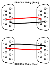
What I gathered from Wikipedia, etc:

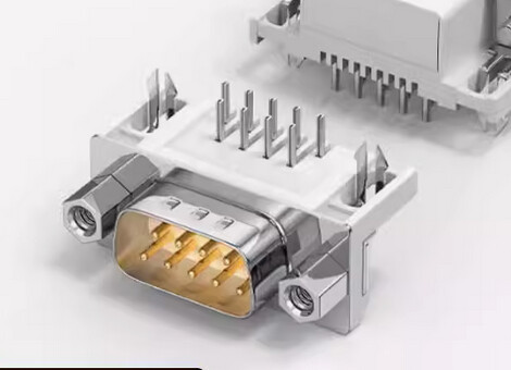
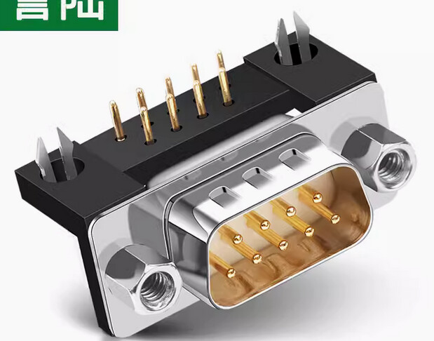
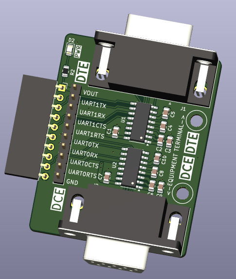
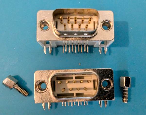
  • Male connector is Data Terminal Equipment (DTE), what you’d see on the back of a computer (in a forgotten time)
  • Female connector is Data Control Equipment (DCE), what you’d see on the back of eg a modem (but not really, modems had DB25 as I recall, but you get the point)
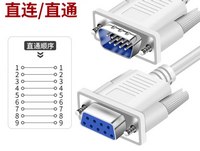
  • Serial cables are 1:1, wired straight through
  • The DCE side has TX/RX and CTS/RTS swapped, so a straight through cable works properly
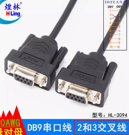
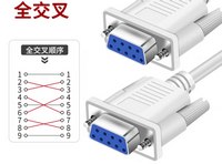
  • None of this is standard at all, so you end up with a mess of null modem cables (crossing RX/TX, sometimes CTS/RTS, sometimes with a few pins tied together to fool equipment into thinking something is attached, these are all over too)

Screenshot_20240716_094657

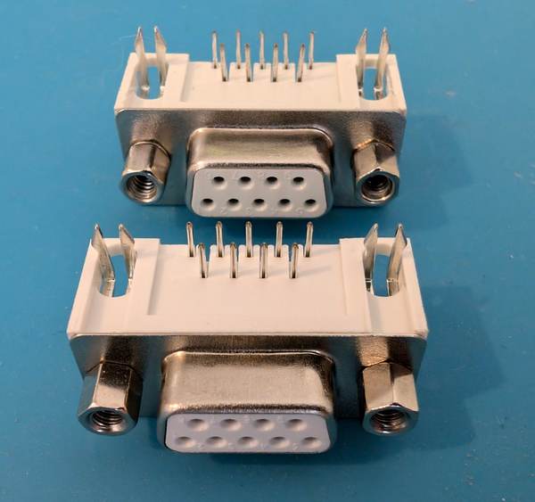
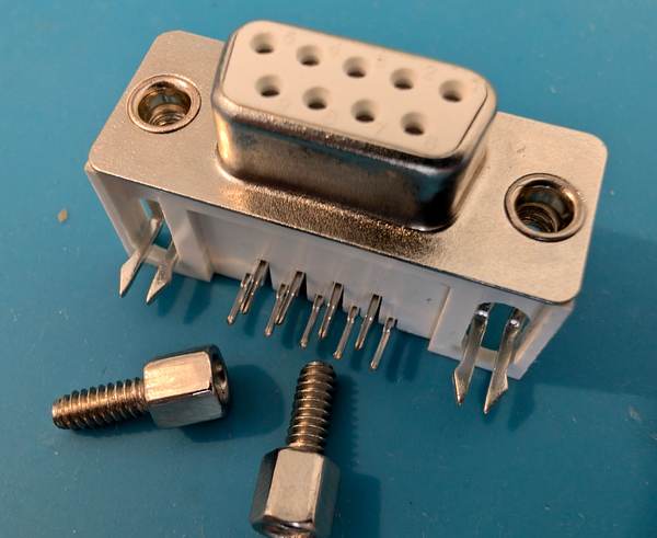
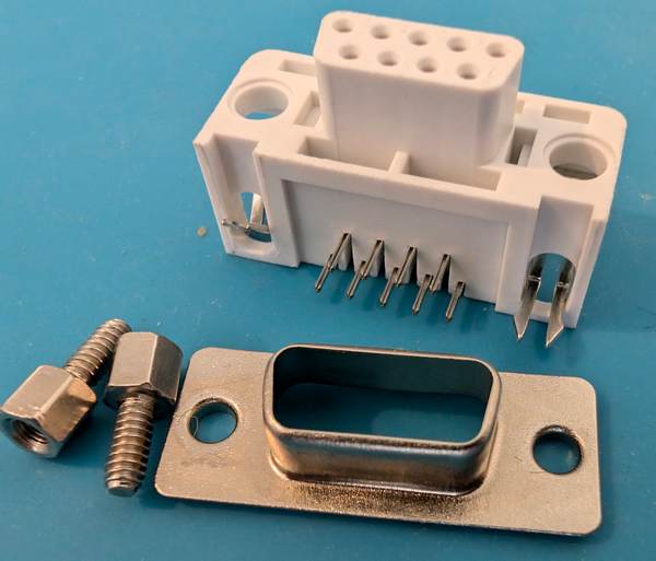
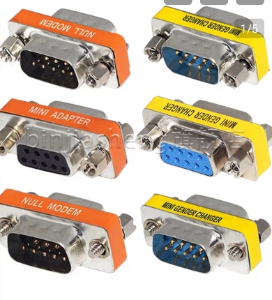
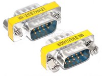
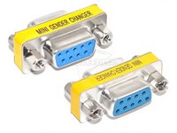
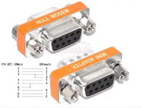
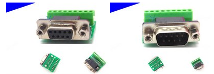
Then there are gender changers and null modem adapters like these. The gender changers are inexpensive (1.8kuai), the null modem are a lot more (8.5kuai).

20240716_095103

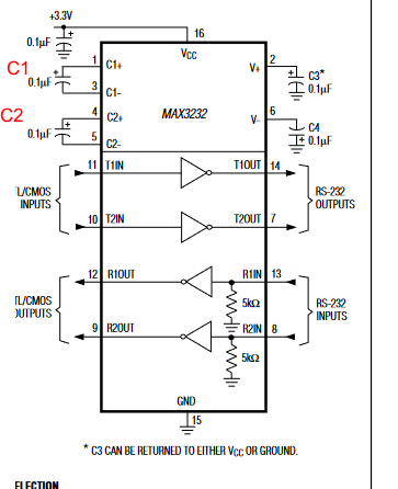
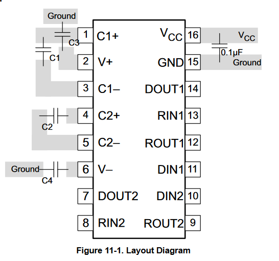
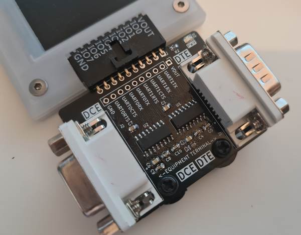
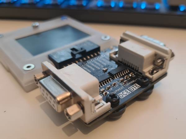
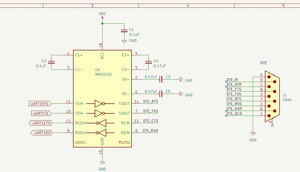
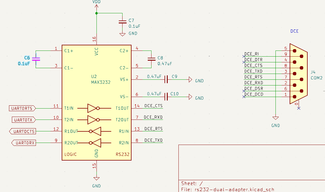
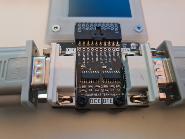
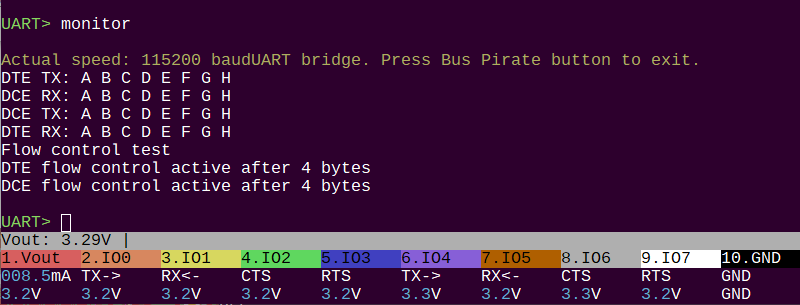
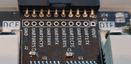
Currently there is one DTE and one DCE on the board, which is connected by a 1:1 male:female serial cable.

I think it’s feasible to include one male to male and one female to female adapter with the plank. However, that won’t swap the pins, so it is more handy for weird connections or when you lack the proper cable, than it is for using the ports properly. The null modem adapters will probably be available in the store as an option - note that they only swap RX/TX, not CTS/RTS.

Null modem cables are probably a cheaper option than the adapters, but also bulkier. I found a cable supplier that provides enough info on the cables to know the correct pinout.

Still to-do:

  • Finish test program
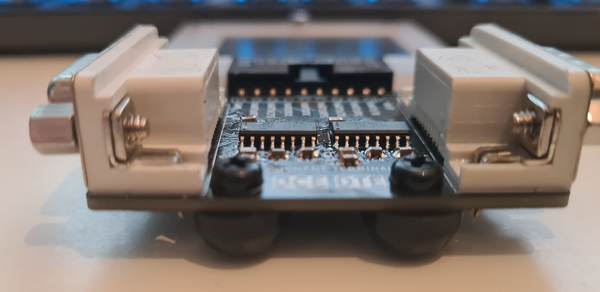
  • Taller standoffs to support the weight of the board

Feedback requested

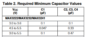
Genuine Maxim 3232s are rated for 235kbps (125kbps at full load) transmission speed, but cost more than $1 per chip.

Clones, I like HGSemi, cost peanuts and claim to work at 250kbps (light loads I assume).

This is pretty old tech, and I assume most max speeds are 115kbps, so I have no problem using a clone personally. However I’d welcome any feedback.

This might be a good opportunity to do a “HQ” vs budget version of the board. One with $$$ chips, and one with $ chips. I’d like to do this on a project to demonstrate what happens when you “bargain” with your Chinese supplier. Usually you don’t get a better deal, you get poorer quality at a fair price.

This board can be in production by end of week if I get some kind of test command going and choose a standoff (7mm or so).

1 Like

It looks to be working. Will make up a second board with the HGSemi chips to make sure they work and try a test with 2 Bus Pirates.

2 Likes

This is a work in progress for the eventual docs.

Dual RS232 Planks

Plank Transceiver Chip
Dual RS232 “HQ Maxim/ADI MAX3232CSE+
Dual RS232 “Budget HGSemi MAX3232EIM

Serial World Accessories

Type Connector 0 Connector1 Wiring Length Wire
Common cable Male Female 1:1 1 meter 30AWG
Cross-over cable Female Female RX/TX, CTS/RTS swapped 1 meter 30AWG
M:M Gender changer Male Male 1:1 - -
F:F Gender changer Female Female 1:1 - -
F:F cross-over adapter Female Female RX/TX, CTS/RTS swapped - -
Female breakout Female Screw terminal - - -
Male breakout Male Screw terminal - - -

Common

Screenshot_20240717_114535
The most common serial cable. Connects a male (usually PC/terminal/DTE) to female (usually equipment/DCE). Straight through 1 to 1 wiring.

Cross over

Screenshot_20240717_114543

Also called a null modem cable. Connects two male (usually PC/terminal/DTE) ports. RX/TX and CTS/RTS are swapped so that two normally master devices can communicate.

Signal 0 Pin 0 Direction Pin 1 Signal 1
DCD 1 1 DCD
RX 2 3 TX
TX 3 2 RX
DTR 4 6 DSR
GND 5 - 5 GND
DSR 6 4 DTR
RTS 7 8 CTS
CTS 8 7 RTS
RI 9 9 RI

Gender Changers

Screenshot_20240717_114850 Screenshot_20240717_114500

Female to female and male to male gender changers. Used with a common cable to interface odd devices, or with odd cables to save the day.

Cross over adapter

Screenshot_20240717_114452

Turns a common cable into a null modem cable that connects two normally master (PC/terminal/DTE) devices. RX/TX and CTS/RTS are swapped (and a few others…).

Signal 0 Pin 0 Direction Pin 1 Signal 1
RX 2 3 TX
TX 3 2 RX
DTR 4 6&1 DSR/DCD
GND 5 - 5 GND
DSR/DCD 6&1 4 DTR
RTS 7 8 CTS
CTS 8 7 RTS
RI 9 removed 9 RI

Breakouts

Screenshot_20240717_115008 Screenshot_20240717_115018

Breakout male and female connectors to screw terminals.

I’m torn on this one. It’s not something we make, but it is inexpensive and useful for hacking.

1 Like

They also sell breakouts for CAN. I can grab a photo tomorrows.

Also, heres an oversimplified reference;
image

I often work with RS232 connections, so this plank would be something I’d get when it becomes available.

Some random thoughts from scrolling through this thread:

Very good that you added standoffs. This is something I wish some other planks, like the ZIF-flash adapter, also had.

I have good experience with the 3Peak TP3232N-SR transceiver, TP3232N-SR 3PEAK | C81661 - LCSC Electronics - they go up to eleven, äh, 470Kbps

When dealing with RS232, mismatching gender and mismatching pin swapping is extremely common. Like unless you have dealt with the exact devices before, you nearly always need to figure out the correct adapters first.

When dealing with the D-Sub connectors there is no other way to fix this except having the right gender changers at hand. So including a pair is a very good idea.

But why rely on external null modem adapters when you think about making them an extra item in the shop? And also their layout isn’t exactly standardized, you might not only want RX/TX swapped, but also RTS/CTS.

Since you already make a PCB, why not make it a tad bigger and build in a set of small switches that allow swapping the pins easily? Small SMD switches are really cheap. When you use a DPDT switch, you would be able to select RX/TX swapping with one switch, RTS/CTS with another. Something like this: MST22D18G2 125 SHOU HAN | C2906280 - LCSC Electronics

2 Likes

Good suggestions, thank you. Yes, anything large is getting standoffs in the next revision. DIP8, SOP8, IC/SIM card.

I actually have a sample of that 3Peak I bought for this project :slight_smile: Ok, if we do another run of “budget” boards I’ll try that one.

I’d like to remark on the connector gender DCE/DTE thing. As I can gather from the above thread, the plank has one of each gender DB-9 wired as DTE/DCE accordingly. I wholeheartedly agree with that. To do a MITM analysis that is the correct way IMHO. You can just unplug the normal connection and insert the plank into the path, using one additional, and normal, cable.

I would also request the addition of a pin header style of connectors so one could tap into the more common logic-level serial interface (you’d need a jumper so the transmitting signals don’t collide). Then there’s the question of WHAT logic level pin header to use? I’ve given up on there ever being a standard for these things. I suggested one before ( see this Hackaday article ), but honestly just a three or four pin header meets 98% of typical use cases.

2 Likes

I ordered one of the new planks and intended to turn my old version into exactly this for OBDII development. I agree that there is no standard, nor will be. From my experience, pending on what your working on, in some corner cases Ive found it can change depending on something as simple as baud rate or protocol.

2 Likes

Looking at this, is the intention that the unpopulated pins can be used for measurements?

It would be nice if there were the same unpopulated pins on the rs-232 side of the plank to make it easier to wire into non standard items vs cobbling together a DB-9 connector?

Or am I being dumb and looking at the plank incorrectly?

image

Do you mean the 1x10 row of unpopulated header? On this plank all pins are in use, so they can’t really be taken for other functions. It’s not impossible, with caveats such as only using the pins that are inputs to the RS3232 (not driven).

This unpopulated breakout of all Bus Pirate signals is common to all planks, and is just there for my (and your) development pleasure. Testing, debugging, or breaking out pins you want to use for another function.

image

For RS232 side breakout we included a screw terminal thing like this in the cable kit. However, breaking out those signals is a good idea. This is the first plank where we have this concept of “internal and external” signals.

It seems like we have a couple updates for a rev2 board:

  • breakout RS232 signals
  • Double throw switches to select pinout
3 Likes