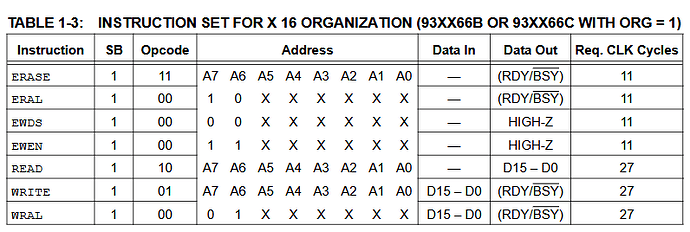
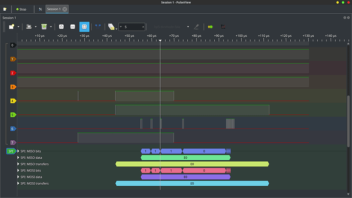
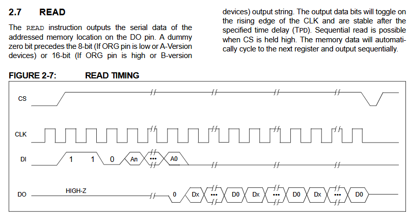
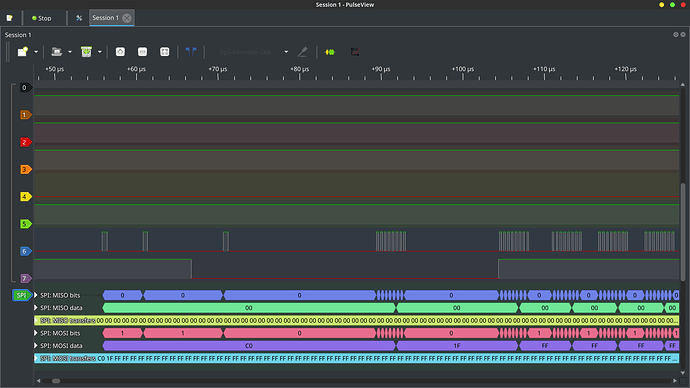
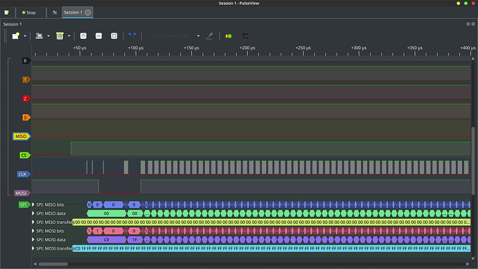
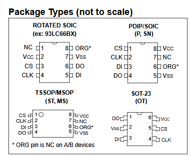
That looks like an weird one. You’ll need to check a pin level to see if it is in 8 or 16 bit mode
When the ORG* pin is connected to VCC, the (x16)
organization is selected. When it is connected to
ground, the (x8) organization is selected.
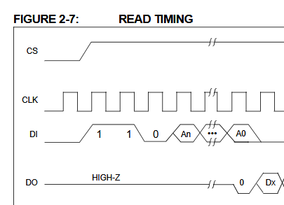
The Start bit is detected by the device if CS and DI are
both high with respect to the positive edge of CLK for
the first time.
DI must be high start
So it has a special start condition, and non divide by 8 word lengths
My recommendation is to use 2wire mode. It is high impedance, so use pull-ups. Then tie DO and DI together with a resistor as mentioned on datasheet section 2.2. Generate the start and op-code with bitwise commands, then read the bytes out with r:256 or whatever. It would be super similar to the SLE4442 tutorial.
I probably missed a LOT of nuance, just skimmed the datasheet.
We need to add a 3wire mode with bitwise operators as well. I’ve started hacking the 2wire PIO program.
I believe this should do it:
Summary
;
; Copyright (c) 2020 Raspberry Pi (Trading) Ltd.
;
; SPDX-License-Identifier: BSD-3-Clause
;
; Based on the PIO I2C example
.program hw3wire
.side_set 1 opt
; TX Encoding:
; | 15:10 | 9     | 7:0  |
; | Instr | X | Data |
;
; If Instr has a value n > 0, then this FIFO word has no
; data payload, and the next n + 1 words will be executed as instructions.
; Otherwise, shift out the 8 data bits
;
; The Instr mechanism allows individual pin sequences to be programmed
; by the processor, and then carried out by the state machine at defined points
; in the datastream.
;
do_byte:
    set x, 7            side 0b0; Loop 8 times
bitloop:
    out pins, 1         [7] ; Serialise write data (all-ones if reading)
    nop             side 0b1 [6] ; SCL rising edge (was 2)
    in pins, 1             [7] ; Sample read data in middle of SCL pulse
    jmp x-- bitloop side 0b0 [7] ; SCL falling edge
    mov isr, null              ; Reset the input bit counter
public entry_point:
.wrap_target
    out x, 6                   ; Unpack Instr count
    jmp !x do_byte             ; Instr == 0, this is a data record.
    out null, 32               ; Instr > 0, remainder of this OSR is invalid
do_exec:
    out exec, 16               ; Execute one instruction per FIFO word
    jmp x-- do_exec            ; Repeat n + 1 times
.wrap

% c-sdk {
#include "hardware/clocks.h"
#include "hardware/gpio.h"
#include "pirate.h"

static inline void hw3wire_program_init(PIO pio, uint sm, uint offset, uint mosi, uint sclk, uint miso, uint32_t freq) {
    pio_sm_config c = hw3wire_program_get_default_config(offset);

    // IO mapping
    sm_config_set_out_pins(&c, mosi, 1);
    sm_config_set_in_pins(&c, miso);
    sm_config_set_sideset_pins(&c, sclk);

    sm_config_set_out_shift(&c, false, true, 16);
    sm_config_set_in_shift(&c, false, true, 8);

    //with delays, there are 32 instructions per bit IO
    //we should maybe reduce this to have more accuracy around 1MHz
	float div = clock_get_hz(clk_sys) / (32 * 1000 * (float)freq);
	sm_config_set_clkdiv(&c, div);

    uint32_t pins = (1u << mosi) | (1u<<sclk) | (1u<<miso);
    uint32_t dir = (1u << mosi) | (1u<<sclk);

    //io pins to inputs
    //bus pirate buffers should already be configured
    pio_sm_set_pindirs_with_mask(pio, sm, dir, pins); //read pins to input (0, mask)
    pio_gpio_init(pio, mosi);
    pio_gpio_init(pio, sclk);
    pio_gpio_init(pio, miso);

    // Configure and start SM
    pio_sm_init(pio, sm, offset + hw3wire_offset_entry_point, &c);
    pio_sm_set_enabled(pio, sm, true);
}

%}
