I am using a sparkfun Bus Pirate v3b (see below) for I2C with a 12-bit DAC (MCP4725) to generate Vout between 0-5V. When I tried this with USB-provided Gnd and +5V from the buspirate, I was not happy with the noise of the Vout from the DAC (RMS was ~4mV, higher than my single-bit voltage steps). I attributed this to my USB noise, so I made a battery-powered voltage reference (RMS of that was lower than 0.1mV). This voltage ref was my first PCB, so I apologize in advance for my silly question.
How do I provide the (noise-free) Gnd and the +5V from the voltage ref to the BusPirate pull-up resistors and my DAC? If I connect the DAC directly to Gnd and +5V from the reference and not use the pins from the BP, I can’t communicate with the BP (i.e. no pull-up resistors etc). If I understand this right, the following page states that I can use the BP with an external power source by connecting the Gnd and +5V pins on the BusPirate to the external source (i.e. my voltage reference). So I tried this, but this just brought back the USB noise to the DAC.
Those docs are for Bus Pirate 5 which is a totally different beast than v3 (ARM, display, variable output regulator, 100MB storage, etc etc).
Looking back at the v3 hardware - the pull-ups are supplied via the VPU pin. So Attach your reference there. Then attach the reference as the power supply to your DAC (Y shaped connection) and you should be good to go
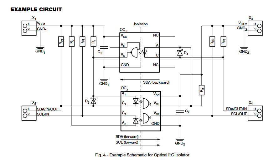
One is a two-in-one package and uses a few tricks to make data bidirectional.
This is the best possible isolation.
Bus Pirate pullups and input isolator (top one) powered by bus pirate 5volts (or 3.3?)
DAC side pullups, DAC, and second optoisolator powered by the reference.
This then isolates the DAC from any Bus Pirate power supply noise as well as any ground noise (which, I mean ground is also in the USB cable and shared with your whole PC so it can be a significant source of noise as well).
Note that the above circuit does not support I2C clock stretching if you’re using that feature of the DAC.
Thank you, Ian. Just tried this (VPU to +5V on the v-reference, ground on BP to ground on v-refernece). Sadly, the noise is there (5mV peak-to peak). So I need to read on the optical isolation. It’s good to learn anyway, b.c. I am sure this issue will keep coming up in future projects.
I do not even know what clock stretching is :), and my DAC technical sheet does not mention it, so I am prob not using it then. I am currently running at 50kHz, and I am unlikely to need higher speeds.
That makes sense. Clock stretching is when the device holds clock low until it is ready for the next command. It’s more common with ADCs. If support was needed, then both clock and data need to be bidirectional. Not a big issue, just copy the SDA design twice. You don’t need it though.
Let us know what you come up with and how well it works!
I have an update on this. I got a galvanic isolator (ADuM1250) and isolated the DAC from the USB ground and power that way. The AdM 1250 was easier for me than implementing 2 optical isolators. The communication through the Bus Pirate was very helpful , b.c. I was able to debug along the way. Many thanks again for your feedback!
Another small numerical update on this for closure. Typical output noise I am getting from a 12-bit MCP4725 DAC controlled by a USB-PB v3b, with an ADuM1250 isolator between the BP and the DAC, is 0.8…1.0mV (peak-to-peak). The DAC and the DAC side of the isolator are powered by 0-5V rail from a 5.000v TI 5050 reference, in turn powered by a 9V battery. The noise from the reference is ~0.1mV peak to peak (which is the detection limit of my oscilloscope).
This noise is much lower than the 5mV i was initially getting w/o the isolator. One can probably do much better (I’ve found posts on on a Raspi forum about folks getting noise under 20uV with this DAC), but I am happy with this result for now.