Hello everyone,
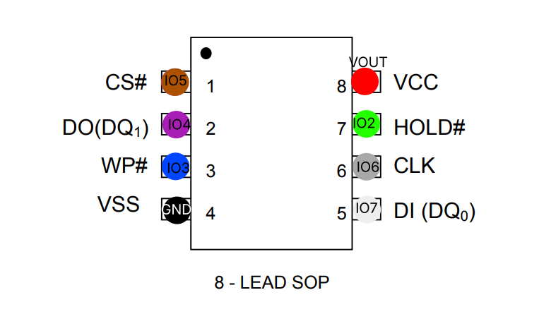
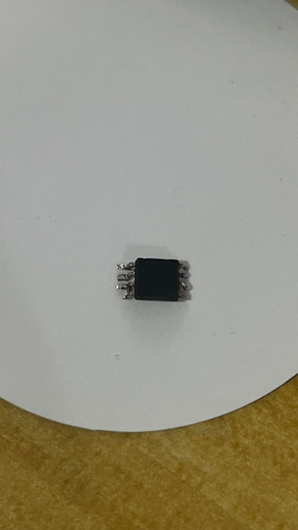
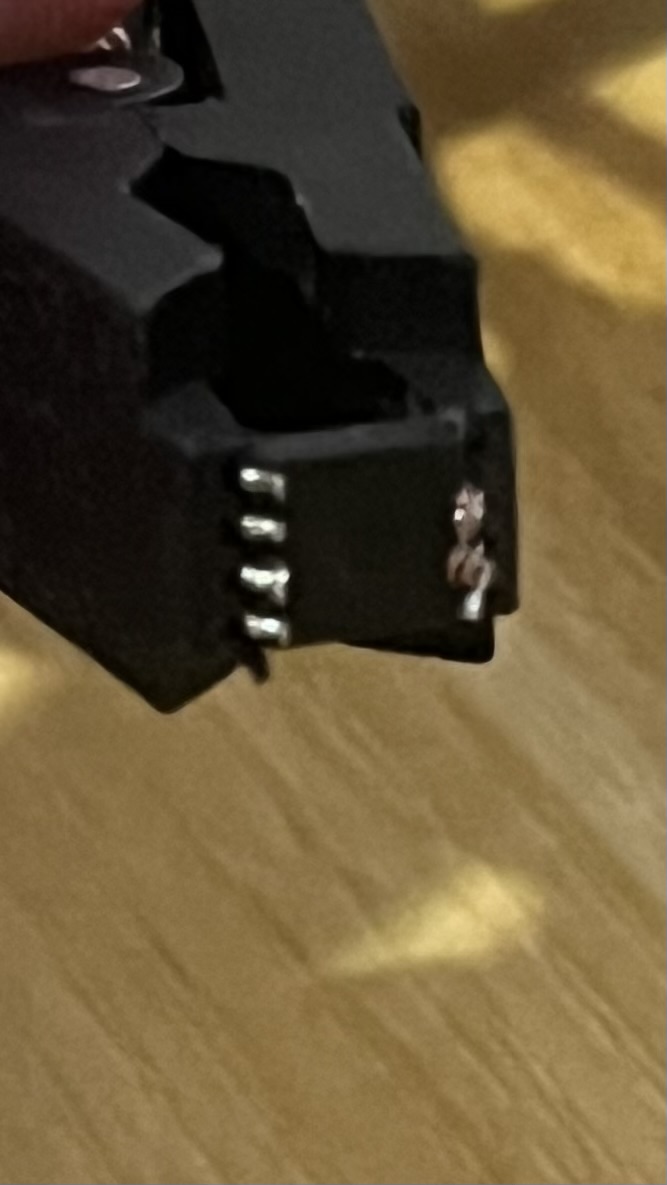
I have a Bus Pirate v5 Rev 10 that I have connected with a SOP-8 clip to a EN25S80 flash memory.
I’m trying to communicate with the chip but it’s not giving me anything. Not the device manufacturer ID, type ID nor capacity ID. I’ve tried via SPI setup according to the documentation, and I’ve attempted to use flashrom as well.
The device which the flash memory is on boots up normally so the flash memory itself should be fine. I am not sure why it’s not working. Any help is greatly appreciated.
I’ve tried SPI mode 0 and mode 3 (both supported by the flash memory), but no dice with either of them. I’ve tried the slowest possible speed as well. With pull up resistors it reads 0xFF everywhere, and without it reads 0x00.
Current settings are as follows:
Bus Pirate 5 REV10
Firmware main branch @ da21ba2 (Jan 14 2026 11:33:09)
RP2040 with 264KB RAM, 128Mbit FLASH
S/N: 28432F0B134063E4
Storage:   0.10GB (FAT16 File System)

Configuration file: Not Detected
Active binmode: SUMP logic analyzer
Available modes: HiZ 1WIRE UART HDUART I2C SPI 2WIRE 3WIRE DIO LED INFRARED JTAG
Active mode: SPI
SPI speed: 1 kHz
Data bits: 8
Clock polarity: Idle LOW
Clock phase: LEADING edge
Chip select: Active LOW (/CS)

Display format: Auto
Data format: 8 bits, MSB bitorder
Pull-up resistors: OFF
Power supply: OFF
Frequency generators: OFF
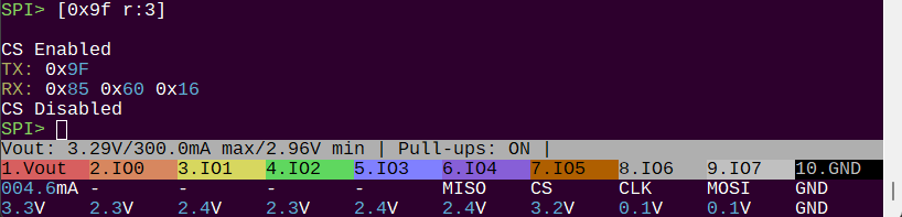
Here’s some output when I enable/disable pull up resistors and send the command to release from power down mode and try to read some bytes. (I also set IO2:HOLD# and IO3:WP# to HIGH).
SPI> A 2; A 3
IO2 set to OUTPUT: 1
IO3 set to OUTPUT: 1
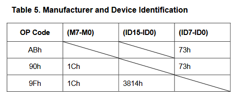
SPI> [0xAB 0x00:3 r:10]
CS Enabled
TX: 0xAB 0x00 0x00 0x00
RX: 0xFF 0xFF 0xFF 0xFF 0xFF 0xFF 0xFF 0xFF
0xFF 0xFF
CS Disabled
SPI> p
Pull-up resistors: Disabled
SPI> [0xAB 0x00:3 r:10]
CS Enabled
TX: 0xAB 0x00 0x00 0x00
RX: 0x00 0x00 0x00 0x00 0x00 0x00 0x00 0x00
0x00 0x00
CS Disabled
I’ve also attempted to use flash probe:
SPI> flash probe

Initializing SPI flash...
Flash device manufacturer ID 0x00, type ID 0x00, capacity ID 0x00
Error: SFDP signature error. It must be 0x50444653 'SFDP'
Warning: Read SFDP parameter header information failed.
Warning: The chip does not support JEDEC SFDP.
Searching flash chip database for 0x00 0x00 0x00
Error: Flash device not found
Error: device not detected
As well as force reading exactly all the bytes available on the chip (per documentation 1,048,576 bytes), no dice there either.
SPI> flash read -o -b 1048576 -f test.bin
Initializing SPI flash...
Flash device manufacturer ID 0xFF, type ID 0xFF, capacity ID 0xFF
Error: SFDP signature error. It must be 0x50444653 'SFDP'
Warning: Read SFDP parameter header information failed.
Warning: The chip does not support JEDEC SFDP.
Searching flash chip database for 0xFF 0xFF 0xFF
Error: Flash device not found
Error: device not detected
Force read of unknown flash chip
Using command 0x03, reading 1048576 bytes
Dumping to test.bin...
[-------------------C]
Dump OK
And when I do hexdump on the file it’s empty.
Lastly I’ve tried to use binmode with flashrom (both specifying the chip with -c “EN25S80” and without specifying it) to no avail.
Anyone have any idea what I am doing wrong here? Any help is greatly appreciated.