Help understanding I2C?

I’ve been having trouble talking with an I2C device, where only the first byte (on of the device’s R/W address pair) is ACK’d, and all other bytes get NACK’d.

history

HW / FW combos tried:

  • BP6 on 3d7b985 (~2025-05-19)
  • BP5 on db84e03 (2025-03-22)

I thought it might be a hardware issue on the connected device, so I disconnected the first and connected a second (identical) I2C device. I’m still getting NACK to everything except the first byte, at both 10kHz and 100kHz.

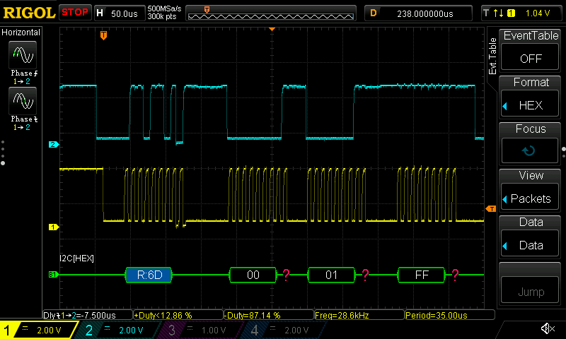
Device I2C address == 0x36, so R/W address pair is 0x6D / 0x6C.

Command sequence is simply entering I2C mode, enabling pullups, enabling 3V3 with max 100mA, and then doing a basic transfer:

  • 0x6D is the I2C read address
  • 0x00 is the register base, STATUS_BASE
  • 0x01 is the “read chip id” function that should return a single byte
m i2c
P
W 3.3 100
[ 0x6D 0x00 0x01 r:1 ]

Result:

I2C> [ 0x6D 0x00 0x01 r:1 ]

I2C START
TX: 0x6D ACK 0x00 NACK 0x01 NACK
RX: 0xFF NACK
I2C STOP

Due to timezones, if you have specific information that you’d like me to collect, or other things to try, let me know.

Solution

Turns out I misread how to interact with the device, and didn’t have the background in I2C to realize it. To read from the device takes two commands:

  • First send the write I2C address, the register base, and edge/function (three bytes), without also sending the device data
  • delay if needed … device/edge/function specific.
  • Then send the read I2C address, and read the resulting data

This works perfectly:

I2C> [ 0x6C 0x00 0x01 ] d:8 [ 0x6D r:1 ]

I2C START
TX: 0x6C ACK 0x00 ACK 0x01 ACK
I2C STOP
Delay: 8us
I2C START
TX: 0x6D ACK
RX: 0x55 NACK
I2C STOP

Thanks to Ian, for helping me understand what that wording means!

Hopefully, my sharing my ignorance and learning will be helpful to other learners of I2C.

3 Likes

Can I have a look at the data sheet?

1 Like

I’ve only found one old datasheet that describes the SeeSaw protocol:

Prior to finding that, I started documenting it in this thread.

No matter what second byte is sent, I get a NACK. Here, I’m just trying to read the chip id … not technically required when you know what’s connected, but it’s the simplest command … just reads a hard-coded value from the I2C device firmware. The NACK is reported when sending the second byte:

I2C> [ 0x6D 0x00 0x01 r:1 ]

I2C START
TX: 0x6D ACK 0x00 NACK 0x01 NACK
RX: 0xFF NACK
I2C STOP
I2C> [ 0x6D 0x00 0x01 d:500 r:1 ]

I2C START
TX: 0x6D ACK 0x00 NACK 0x01 NACK
Delay: 500us
RX: 0xFF NACK
I2C STOP
I2C>

The board has built-in pull-ups. There is no change in behavior when I disable the buspirate’s pullups.


Stuff that works

Scan command

The scan command finds the device, which also confirms the 0x6D read address / 0x6C write address.

I2C> scan
I2C address search:
0x36 (0x6C W) (0x6D R)

Found 2 addresses, 1 W/R pairs.

Sending only the address

If I only send the first byte, I properly get an ACK:

I2C> [ 0x6D ]

I2C START
TX: 0x6D ACK
I2C STOP
I2C>

Sending to invalid address

If I send to an invalid address, I properly get a NACK:

I2C> [ 0x44 ]

I2C START
TX: 0x44 NACK
I2C STOP
I2C>

BusPirate setting to 3.3V

As expected, this works fine.

BusPirate enabling / disabling pullups

When I enable the pull-ups, all the BP IO show ~3.3V.

When I disable the pull-ups, only BP IO0 (SDA) and IO1 (SCL) show ~3.3V (pulled up by the SeeSaw board, as expected). The remaining BPIO show 0.0V, as expected.

BusPirate setting to 5V

As expected, this works fine. The SeeSaw board bumps both SDA and SCL to 5V as a result. All as expected.

Rigol DS1054

Well, it’s working properly AFTER I disabled the inverted input option on the probe. I had my multimeter, the DUT, and the probe all connected (Aux cable helped).

Only took me 80 minutes or so to track down why triggers and display were so far off on the scope. :rofl:

I don’t use these tools often enough to be efficient with them. I don’t recall ever setting the input to be inverted, so had to convince myself by connecting the probes to plain old VOUT first.

Over-current detection on BP5

Yeah, I shorted stuff multiple times. Love that the BP5 kept the magic smoke in!

Next steps

I hope to get the comms traced on the scope. Maybe I’ll see something, or maybe it will show something useful to others here.


2 Likes

Well… it seems possible that I’m just sending the wrong stream of bytes to the device. The scope shows that no data is coming back, and that only that first byte is being ACK’d by the device:

You can easily see where it’s pulling down SDA in response to the
address. Then, it doesn’t respond to the 0x00 byte being sent.

Am I decoding the signal correctly? If so, maybe I’ve killed these two devices?

2 Likes

A register read is accomplished by first sending the standard I2C write header,
followed by the two register bytes corresponding to the data to be read. Allow a short
delay, and then send a standard I2C read header (with the R/W bit set to 1) to read the
data.

it seems like the typical I2C dance. Use a write to set the address pointer, then read back from the read address. The pattern is covered in the updated 24C02 device demo. That would explain why you are not getting any ACKs, it expects you to ACK anything out the read address.

Without getting too far into the weeds yet, I think something like this is needed:

[ 0x6c 0x00 0x01]

First, use the write address to setup the read pointer to the thing you want to read.

[ 0x6d r]

Then use the read address to pull data from the device.

The datasheet is not immediately intuitive, so I’m not 100% certain these are the correct commands. This is a guess based on your attempts posted above.

2 Likes

Ah! I didn’t realize that each time the address is used, that it “switches” the data transmission direction. That definitely makes the protocol simpler. :slight_smile:

Updated the first post to reflect my learnings.

2 Likes