I2C Scan with multiple targets

I have two questions relating to a magnetometer connected via I2C.

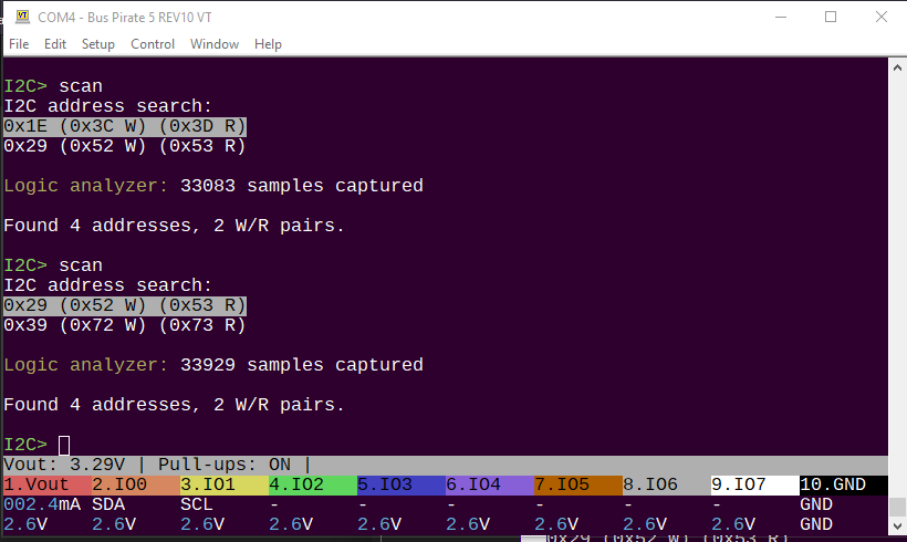
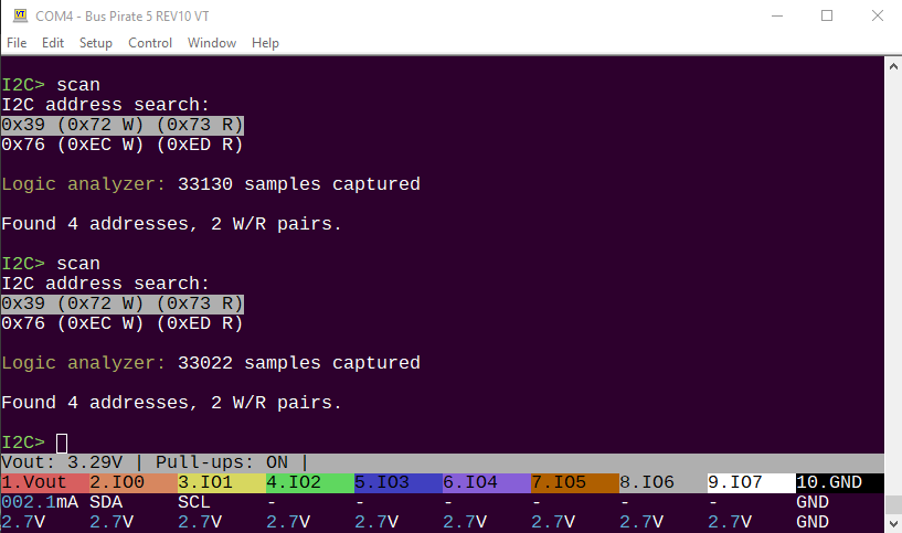
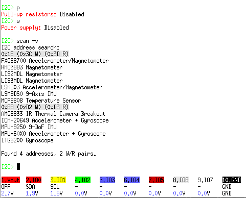
  1. I’m trying to debug a magnetometer *1 and an accelerometer *2 on a Sony Spresense using I2C, and I see some curious behavior. If I have just the magnetometer connected, and run “I2C> scan -v”, it finds the magnetometer, though not at the correct address as given in the data sheet. If I connect the accelerometer, I don’t see either device in the BP “scan” output. However, under Nuttx on the Spresense, I have the “i2c” tool installed, and it shows both devices attached.

So the Spresense sees both devices, and the BP sees neither. I’d question my wire connections, but since the Spresense sees both, I think it has to be something else. Any idea?

  1. The other question relates to I2C IDs. In the data sheet for the HMC5883L magnetometer, it says the address is 0x1E (7 bit), but it actually appears at 0x0d. The Spresense also lists the device at 0x0d, so I think it’s plausible. “scan -v” lists the device as “MLX90393 3-Axis Magnetometer.” Is that from an internal table of possible devices at given I2C IDs, or is that read from the device itself? Do I2C devices sometimes have the wrong ID?

#1: HMC5883L GY-273 Three-axis Magnetic Field Sensor
#2: Adafruit Triple-Axis Accelerometer - ±2/4/8g @ 14-bit - MMA8451 : ID 2019 : Adafruit Industries, Unique & fun DIY electronics and kits
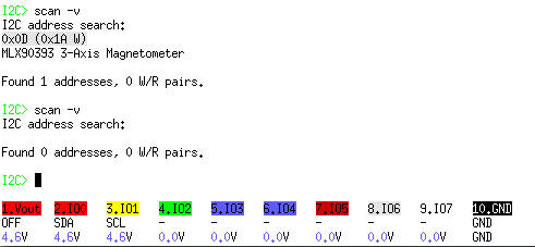
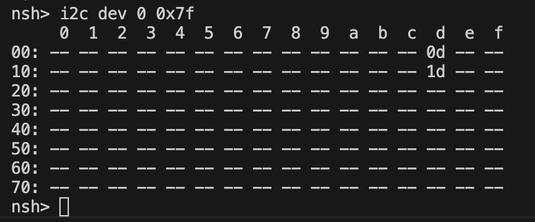
Here’s the other screen capture.

Ok, I think I’ve figured part of it: the 0x0d address looks like it’s actually a QMC5883, instead of a HoneyWell HMC5883L. I got sold a fake part, I guess. So ignore that part of it.

Hi @evil-aaronm ,

I’ll have a look at those data sheets and get back to you shortly.

What firmware version are you using?

Are you able to use the follow along logic analyzer to see what’s happening on the bus?

1 Like

Hey, Ian,

I’ll have to read the fine manual to figure out how to use the logic analyzer; I’m not that skilled with it, yet. However, using the BP, my o’scope showed a “typical” I2C scan pattern - lots of SCL and SDA activity on the two channels. The primary difference between the BP and the Spresense scans is that the Spresense takes the clock signal to roughly 400mV, where the BP takes it to about 1.2V. I’m not sure how critical that is. The P and W options are off for I2C. Even with P and W on, the lowest SCL voltage is still around 1.4V.

The QMC5883 data sheet is here:

As mentioned, my “5883” is actually a QMC, instead of a Honeywell.

BP version:
Bus Pirate 5 REV10
Firmware main branch @ 62ce168 (2024-11-15T14:23:13Z)
RP2040 with 264KB RAM, 128Mbit FLASH
S/N: 22423D0B134063E4
Storage: 0.10GB (FAT16 File System)

Configuration file: Loaded
Available modes: HiZ 1-WIRE UART HDUART I2C SPI 2WIRE DIO LED INFRARED
Active mode: I2C
I2C speed: 100 kHz
Clock stretching: OFF

Display format: Auto
Data format: 8 bits, MSB bitorder
Pull-up resistors: OFF
Power supply: OFF
Frequency generators: OFF

Thank you for the extra details.

The device name/identity comes from a list inside the Bus Pirate, which I believe is maintained by Adafruit on their github repo ( I forget where I pulled it from). Since there are only 127 possible device addresses there is a lot of overlap. It’s useful when you’re trying to narrow down the identity of an unknown chip.

image

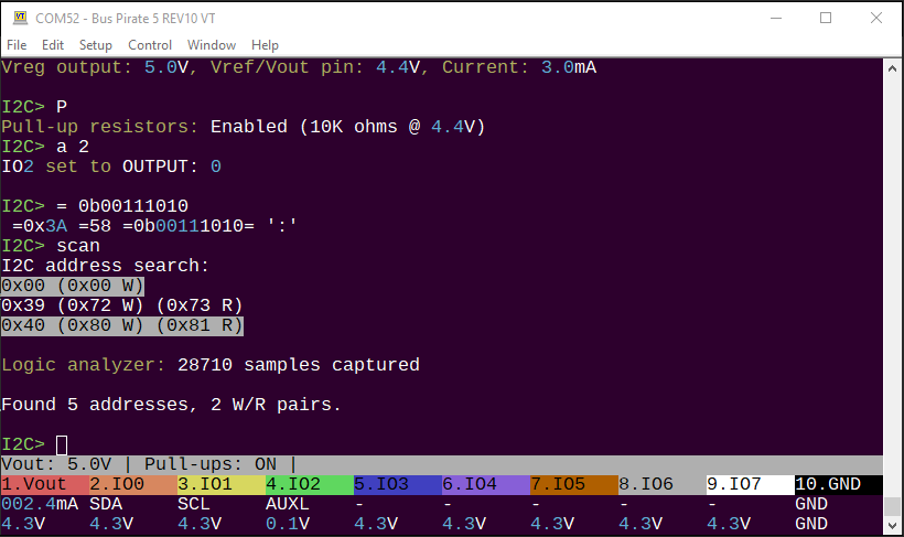
The MMA8451 should show up at 0x1d (0x3a W/0x3b R).

image

The QMC5883L should appear at 0x0d (0x1a W, 0x1B R). It seems like we’re only seeing the write address though, not the read address.

Did a quick check with two devices on I2C scan to make sure it’s working properly.

Both chips are on breakout boards?

I see a 4.6volt supply on the Vout pin, but the onboard power supply is disabled. What is the source of the supply?

The adafruit board has pull-up resistors on both sides of the level shifter, so that part seems ok.

Hum, this might be a clue. It is technically in spec at 5volts, but is it in spec after the 3.3volt level shifter? What is the actual low getting to the chip?

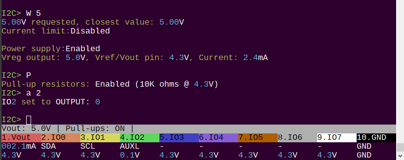
Can you please try the commands in I2C mode:

  • W 5 (enable power)
  • P (enable pull-ups)
  • a 2 (IO2 to output low)

Now check the IO2 voltage, it should be down around 0.1volts.

If you can take the pin low, but not I2C pins, I wonder if there is an interaction between some equipment on the breakout board(s) and the Bus Pirate front end buffers. You could test for this by running the scan without anything connected and then looking with the scope.

If it is a voltage level issue, then the logic analyzer might not be much help, but here are the instructions. It’s very easy to get going on Windows, but needs to be compiled for Linux.

EDIT TO ADD: That firmware is a few weeks old. I recently validated every mode and there are some fixes in the latest firmware.

2 Likes

Please ignore the bad voltage output on this board, it is a prototype I reworked with a 2gbit nand and I broke some stuff in the process.

2 Likes

Both chips are on breakout boards?

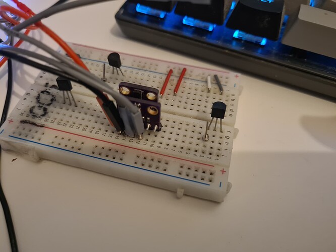
Yes, they have their own carrier boards. They’re connected on a breadboard, using the same + / - voltage source.

I see a 4.6volt supply on the Vout pin, but the onboard power supply is disabled. What is the source of the supply?

It’s coming from the 5v output of the Spresense itself. I have that plugged into the common supply of the breadboard. The red Vout pin is connected to the positive rail, and the ground pin is connected to the ground rail.

Can you please try the commands in I2C mode:

W 5 (enable power)
P (enable pull-ups)
a 2 (IO2 to output low)
Now check the IO2 voltage, it should be down around 0.1volts.

IO2 voltage was 0.1v. However, it didn’t help the BP “scan”, and it actually “wrecks” the bus: it prevented the Spresense from scanning successfully, until I used the BP “#” reset command and reconnected. This was repeatable before and after the firmware update.

Out of curiosity, I disconnected the Adafruit accelerometer, one pin at a time, and checked the scan from BP in each case: it couldn’t find either device until both pins of the accelerometer were disconnected. And, just to be complete, I connected it so that only the accelerometer was connected, and it scanned successfully, there, too. So it’s evidently when both of them are connected, though the Spresense can see both.

Thank you for hanging in there and the additional info.

This is odd. Lowering an unused pin to ground should not have any impact on the scan either way. However, you’ve now enabled the Bus Pirate power supply so you have 2 supplies which isn’t ideal. I should have specified to disconnect any devices, I just wanted to make sure your buffer actually goes low.

Bus Pirate I2C Chips
Vout (5volts) V+/VCC
GND GND
SDA SDA
SCL SCL

What happens if you remove any connection to the Suprasense, and use the Bus Pirate alone? Enable the Bus Pirate power supply (W 5) and pull-ups (P) and scan?

I still think the 1.2V low level is a clue. Are you certain that there is a strong ground connection between the suprasense, the I2C chips, and the Bus Pirate?

You could also open the Bus Pirate and inspect the ground pin soldering to make sure it’s solid. A non-invasive way to test this is (without removing the case):

  • Enable Bus Pirate Power supply (W 5)
  • measure the voltage between VOUT and GND pins and verify it is ~5 volts

I don’t have the sensors you’re using, but I tried combinations of I2C devices from my parts box and couldn’t find any bugs.

These are all cheap/knock-off chips and breakouts, nothing fancy.

Have you tried communicating with a chip directly instead of with scan? For example:

[0x3a] (should ACK)
[0x1a] (should ACK)

I’m sorry I don’t have an immediate solution, and “works for me” doesn’t help get you closer to a solution. Here’s everything I can think of:

  • Suprasense supplying power and being connected at same time is causing issues (remove Suprasense and use Bus Pirate power)
  • Bad ground connection (ensure Bus Pirate is connected to I2C chips ground, check that you can read a voltage between VOUT and GND pins on the Bus Pirate)
  • Damaged Bus Pirate (check output with scope, try to communicate with the chip with FALA enabled - though that might be hard on a Mac)
  • Scan algorithm bug (try directly communicating with the chip [0x3a], [0x1a])

Unfortunately if all these things fail, there’s not much we can do to debug it without a logic analyzer or scope capture to look at.

2 Likes

Just to check, I tested in a similar configuration with the breakouts on a bread board. I want to make sure the Bus Pirate pins are strong enough to handle the capacitance of the breadboard.

Unfortunately I am unable to reproduce the issue.

2 Likes

I took the QMC device out completely. I got a LIS3MDL magnetometer, today, and hooked it up to test it out. It scans very well, in both the BP and the Spresense. The accelerometer doesn’t scan properly with BP, though BP reports “Found two addresses, 1 W/R pairs,” listing the LIS3MDL. I’m gonna say the QMC was just a junk piece of hardware that “sort of” worked, at best. I don’t know why the Adafruit accelerometer isn’t responding properly, but it’s not my primary focus with this project, anyway, so I can live without it.

1 Like

Thank you for the update. I’m going to grab the accelerometer from adafruit and see if I can reproduce the issue. I’m really curious what is going on.

2 Likes

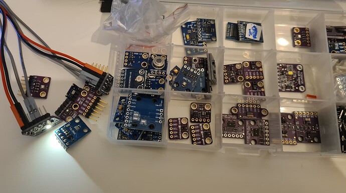
I finally received the Adafruit breakout. It made a very strange journey through the post, the envelope is full of redirection stickers. Weird.

I2C> W 3.3
3.30V requested, closest value: 3.30V
Current limit:Disabled

Power supply:Enabled
Vreg output: 3.3V, Vref/Vout pin: 3.3V, Current: 2.9mA

I2C> P
Pull-up resistors: Enabled (10K ohms @ 3.3V)
I2C> scan
I2C address search:
0x1D (0x3A W) (0x3B R)

Found 2 addresses, 1 W/R pairs.

I2C>

Using these settings I was able to find the board at 50kHz, 100kHz, and 400kHz.

You may need to double check your connections to make sure nothing is in contention when connecting multiple masters to the I2C bus.

2 Likes

And I thought I was persistent. :slight_smile:

I added a gyroscope to the circuit, so now it’ll be a LIS3MDL, and an ITG-3200, so it’s going to have to work. I haven’t powered it up, yet, so I can’t confirm, but I will post back when I test it. Thanks for the update.

Running on battery, and without the QMC chip, it seems to work as expected. So, no problems here, I guess. The QMC chip is less than trustworthy, I’d say.

Thanks for all the assistance!

3 Likes

Thanks for the update, I’m glad you got it going.

2 Likes