Thank you for the extra details.
The device name/identity comes from a list inside the Bus Pirate, which I believe is maintained by Adafruit on their github repo ( I forget where I pulled it from). Since there are only 127 possible device addresses there is a lot of overlap. It’s useful when you’re trying to narrow down the identity of an unknown chip.

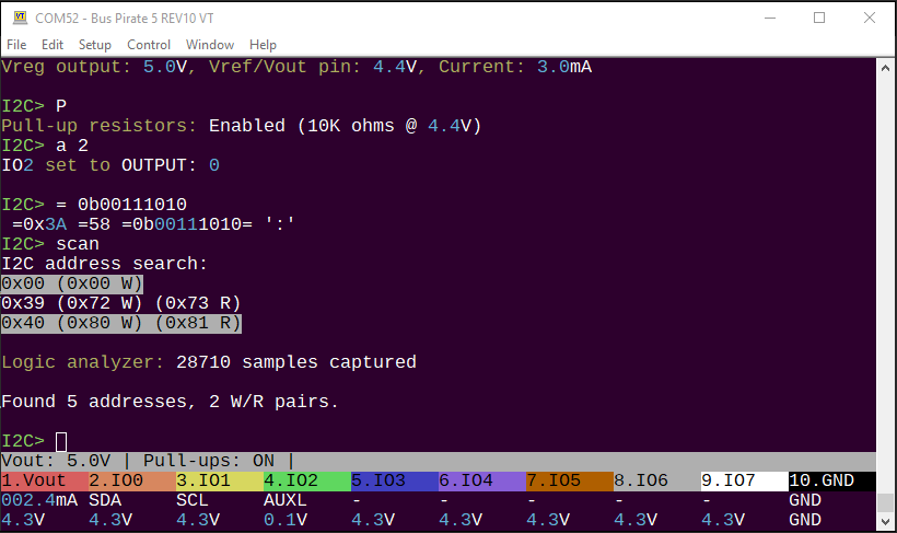
The MMA8451 should show up at 0x1d (0x3a W/0x3b R).

The QMC5883L should appear at 0x0d (0x1a W, 0x1B R). It seems like we’re only seeing the write address though, not the read address.
Did a quick check with two devices on I2C scan to make sure it’s working properly.
Both chips are on breakout boards?
I see a 4.6volt supply on the Vout pin, but the onboard power supply is disabled. What is the source of the supply?
The adafruit board has pull-up resistors on both sides of the level shifter, so that part seems ok.
Hum, this might be a clue. It is technically in spec at 5volts, but is it in spec after the 3.3volt level shifter? What is the actual low getting to the chip?
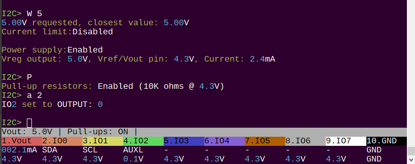
Can you please try the commands in I2C mode:
- W 5 (enable power)
- P (enable pull-ups)
- a 2 (IO2 to output low)
Now check the IO2 voltage, it should be down around 0.1volts.
If you can take the pin low, but not I2C pins, I wonder if there is an interaction between some equipment on the breakout board(s) and the Bus Pirate front end buffers. You could test for this by running the scan without anything connected and then looking with the scope.
If it is a voltage level issue, then the logic analyzer might not be much help, but here are the instructions. It’s very easy to get going on Windows, but needs to be compiled for Linux.
EDIT TO ADD: That firmware is a few weeks old. I recently validated every mode and there are some fixes in the latest firmware.


