I2C Sniffing (BP3 backwards compatibility)

Continuing the discussion from I2C "promiscuous/sniffing" mode?:

Summary thus far...

  • Billms posted asking for way to snoop on I2C, specifically on between two HDMI devices.
  • Ian noted best bet is Logic Analyzer mode of the BP5 + Pulseview / Sigrok for decoding
  • MS3FGX asked if this meant BP3 I2C sniffing features will never arrive

@MS3FGX

As you know, technically, anything that’s missing from the BP5 (but was in BP3) could be implemented eventually. Generally, backwards compatible features have had someone familiar with how they worked on BP3 who drove the feature, provided test cases, etc. This could be Ian, but more often it’s someone who was relying upon the feature in BP3, and wants to secure an upgrade path.

The way I read Ian’s response, he was helping that user move forward with their problem as rapidly as possible, not saying a feature would never be part of main firmware.

Since I am not familiar with the I2C “snooping” feature in BP3, could you help fill in some details on your question for me?

  • What features are you specifically looking for?
  • Are you looking for some type of scripting compatibility, or individual commands, or … ?
  • Can you help me understand some use cases where it’s better to have a built-in capability in the firmware? (vs. capturing a trace for decoding on PC … e.g., if the BP3 allowed to mostly sniff, but then intentionally corrupt transmission in some way? e.g., other types of fault-injection?)

Thanks!

2 Likes

I know I wasn’t in the original conversation, but I used I2C sniffing a lot with the BP3. I’ve also used a logic analyzer with protocol decoding to do the same thing. For me, it depended on what i is was doing.

I used the BP3 in sniff mode to look for certain events and associated data. For example, a micro accessing an I2C EEPROM during some operation to see if I can find secrets or config data. With I2C, it’s easy to turn around and take control of the bus and maybe change that EEPROM data and or pull it out again for more analysis directly with the BP3 bus read/write commands.

On the other hand, I’ve used a logic analyzer to just sit on the bus and capture all traffic, decode it, and use that to reconstruct the contents of an I2C memory device. Depends on how long/how much traffic I needed. Either way, I’d usually do post capture analysis/manipulation in Python.

I can’t speak for @MS3FGX , but that was my main use case for sniff mode.

To be fair, if I needed to do it today, I’d just use my BP3; but it would be nice to have it in the 5. Not a necessity, just a nice to have thing.

2 Likes

Neat. If I understand correctly, the BP3 has some way to:

  1. trigger on specific I2C data, going in a specific direction
  2. after that trigger, “take control of the bus” (e.g., break the connection from the controller device from the target device? … maybe while glitchlessly stretching the clock?)
  3. After taking control of the bus, continue tranfers of data from the BP3 “as if” it were the controller device
  4. After taking control of the bus, continue responding to the controlling device “as if” it were the target device
  5. At some later time, “release control of the bus” (e.g., stop modifying the comms), returning to sniffing mode

Is the above accurate? Is there documentation? Is the documentation enough to for someone starting fresh to do those things?

1 Like

The v3.x I2C sniffer is a state machine that tracks the pins with change notice interrupts. It looks like it is in the terminal and in the binmode.

The RPxxxx is probably capable of running a modification of the existing code fairly well (16MIPs vs 125MIPs). I would guess the PIO is probably the right way to do it.

Here’s a pretty advanced project, MIT licensed, for I2C sniffing on RP2040. We could integrate a variation of that.

I also have a bookmark for an SPI sniffer update from @henrygab that I’ve yet to implement.

And don’t forget @dreg’s PS/2 sniffer.

1 Like

Very soon

3 Likes

No, this is all manual in the console.

I2C is technically a single controller/multiple device bus, but the open collector wiring means anything can be the master. It’s a matter of avoiding collisions.

1 Like

Here’s a short write-up of somebody using the I2C sniffing function on the BP 3, which should help clarify things:

Basically, you could wire the BP in between two I2C devices (here a Raspberry Pi and an EEPROM), start the sniffer macro from within the I2C mode, and see a read-out of the messages going back and forth. From there they could be dumped to file, replayed, etc.

Being able to quickly switch between eavesdropping on the communication between two devices and sending out your own I2C packets was ideal for reverse engineering. Compared to putting the BP into logic analyzer mode, setting up the protocol decoding, capturing, etc.

4 Likes
I2C> [ 0x00 0x01 ]

I2C START
TX: 0x00 NACK 0x01 NACK
I2C STOP
I2C>

s00n01np

Loaded the I2C sniffer on a bare PICO board. It seems to work well.

.define PUBLIC SDA_PIN     0    ; Input for i2c data.
.define PUBLIC EV0_PIN     1    ; Input/Output for bit 0 of event code.
.define PUBLIC EV1_PIN     2    ; Input/Output for bit 1 of event code.
.define PUBLIC SCL_PIN     3    ; Input for i2c clock.

Like many PIO programs, it uses some extra GPIO pins to signal between PIO state machines. These currently separate the SDA and SCL pin. I have not looked closely enough to determine if this can be reasonably changed to match the current I2C pinout.

1 Like

Added a sniff command to I2C mode using the PIO program from pico-i2c-sniff project.

I2C> [ 0x00 0x01]

I2C START
TX: 0x00 NACK 0x01 NACK
I2C STOP
I2C>

Generating I2C output in one Bus Pirate.

val: f001400, ev_code: 1, data:0, ack: 1
val: 1, ev_code: 0, data:0, ack: 0
val: 3, ev_code: 0, data:1, ack: 0
val: f001e00, ev_code: 3, data:0, ack: 1

Sniffing from a second Bus Pirate. It does work.

; Wait for events from the state machines (START/STOP/DATA) 
; and fill the communication FIFO of the APP.
; NOTE: as MOV and IN use PINS, they must be consecutive and in this 
; order (B0, B1, B2): SDA, EV1, EV0. And to know if the event is 
; data or (start/stop), you have to use the JMP instruction that allows 
; you to configure the PIN independently of the PINS.
  • There is indeed an issue with the pin order, but I think I can smoosh it into the correct order.
  • pico-i2c-sniff has a nice ram FIFO so it doesn’t fall behind. That should be implemented using the “big buffer” I assume, but then the logic analyzer can’t be used at the same time. Maybe time to bring in the allocatable mode memory?
  • There is a protocol bug in my latest work. Tracking it down now.
1 Like

How backwards compatible do we want to be?

[0x00+0x00-0x00-]

Old format. [ start, 0x00 data, +/- ack/nak, ] stop.

S 0x00n 0x01nP
S 0x00n 0x01n 0x02n 0x03n 0x04n 0x05n 0x06n 0x07n 0x08n 0x09nP

This is the pio-i2c-sniff way of displaying the data: S start, 0x00 data, a/n ack/nak, P stop.

Everything seems to work ok. The buffer situation needs to be addressed, but first I’ll see if I can modify the pin order to match the Bus Pirate I2C mode.

1 Like
val: f000c00, ev_code: 1, data:0, ack: 1
Sval: 1, ev_code: 0, data:0, ack: 0
 0x00nval: f001e00, ev_code: 3, data:0, ack: 1
P

Success changing the pin order to match the existing I2C mode. I realize the debug output doesn’t look like much, but it is success :slight_smile:

Display Proposal

For the display format, I have a proposal:

  • Change output to old BPv3.x, it is easier to copy/paste back into the terminal.
  • Don’t show acks, only show naks? This way successful transactions can be copied and replayed from the command line without a trip to a text editor (could be command line switch)

Todo:

  • Change output to old BPv3.x, it is easier to copy/paste back into the terminal.
  • Pin labels, including EV0 & EV1 (inter SM communication pins).
  • Help
  • Exit, restore I2C mode
2 Likes

To be fair, I haven’t done this in over a year since I was employed as a hardware pen tester.

I used to use logging in Minicom to “extract”/save the data from the BP3, then had a Python script to scrape through it to remove the acks and other stuff and convert to a straight binary file. Then I’d do whatever I wanted (look for patterns and data, modify, etc). I just liked working with flat binary files, so…

Then a Python script to restore it to BPv3 format with writes or whatever, then paste it back into the minicom.

That would make it cleaner :slight_smile:

There were times when I also used binmode on BP3 to to work with an I2C device. Once, I wrote a Python script to use binmode to auto extract, then decode and format data from the serial EEPROM in a specific device (then that data was used to exploit the device).

How I used the BP3 in I2C mode all depended on how the test was going and what I was finding, but I always started in interactive/console mode to first sniff, then move on from there. Thanks for restoring the sniff mode!

1 Like

In general I think the old format is fine, but I do wonder if it shouldn’t be unified with how the messages are displayed when manually sending I2C from a usability standpoint.

Perhaps it could be an option? The compact BP 3.x style for those who are interested in capturing/manipulating the data, and the verbose and broken out display for those who are more concerned with human readability.

On the subject of capturing the data, is there value to having a function to write the packets to file similar to how the IR capture works?

1 Like

I had similar feelings. The issue becomes speed to spit out all the text.

Core 0 handles all the user interaction. It grabs the sniff and spits out text.

Core 1 handles USB, display, and a few other things.

To make the sniffer more bullet proof, new need one core to grab the sniff and put it in a huge buffer. Core 0 (for reasons related to … Issues) would have to process the sniff onto text and push it into the USB queue processed by core 1.

The original project is less complicated than the bus pirate and so they have a clean split of core 0 shoves in the buffer, and core 1 processes to output and also manages USB.

I’m not sure how it could/would work, but I assume we can also tap DMA as a way to have a big ring buffer. But then RP2040 doesn’t really have a ring buffer mode, it has a ping pong mode. I read that 2350 is a bit better but have not actually seen for myself.

I still need to do some testing to see the pErformace at 1mhz, and also long bus transmissions. It’s not actually that much work for a 125mhz processor to deal with 1mhz/9bits so 110khz output from the PIO. Further ruggedizing may not me needed beyond perhaps a flag to disable LCD and toolbar updates.

2 Likes

The I2C sniffer is ready to merge into main.

  • Top speed seems to be 500kHz
  • I tested up to 512 byte frames without loss of any data

Here’s some preliminary docs markdown to be moved over later:

The Bus Pirate can sniff data on an I2C bus and display the transactions in the terminal.

I2C sniffing is provided via the pico-i2c-sniff project. It uses all four state machines of a PIO to accurately sniff the traffic on an I2C bus at up to 500kHz.

Connections

  • Connect SDA (IO0) to the I2C data pin of the bus to sniff
  • Connect SCL (IO1) to the I2C clock pin of the bus to sniff

Setup

Access the I2C sniffer from I2C mode:

  • m - Select mode
  • 5 - Choose I2C mode

The speed and clock stretch settings have no effect on the sniffer speed. Choose the defaults by pressing enter.

:::tip
Sniffer speed is independent of the I2C mode transmit speed. The sniffer will work up to 500kHz regardless of the I2C speed selected during configuration.
:::

Use

To begin sniffing type the sniff command followed by enter.

Output Format

I2C> [ 0 1 2 3 4]
I2C START
TX: 0 NACK 1 NACK 2 NACK 3 NACK 4 NACK
I2C STOP
I2C>

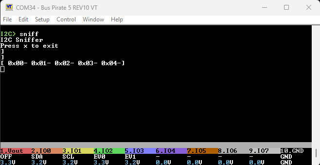
We’ll send this very simple I2C packet using one Bus Pirate, and sniff it with a second Bus Pirate.

  • [ - I2C START bit
  • 0 1 2 3 4 - Four bytes to transmit
  • ] - I2C STOP bit

No actual I2C device is connected, so the bytes will not be acknowledged (ACKed).

[ 0x00- 0x01- 0x02- 0x03- 0x04-]

I2C sniffer results use a similar syntax. Paste them into the I2C mode command line to repeat transactions.

  • [ and ] - I2C START/STOP
  • 0x00 - A byte of data sniffed
  • + and - - Indicates I2C ACK/NAK for each byte

All the bytes are NAKed because there’s no actual device connected.

Options

Type sniff -h to see the most recent options and usage info.

  • q - Don’t display ACKs/+ (success) so it is easier to paste sniffed transactions into the I2C command line. NAKs/- (fail or end of read) will still be displayed.

Good to Know

In sniffer mode pins IO2 and IO3 are used internally to track the I2C bus state. They will be labeled EV0 and EV1, do not make any external connections to these pins.

:::warning
Do not connect to IO2 (EV0) or IO3 (EV1) in I2C sniffer mode.
:::

3 Likes

Been playing around with new sniffing function, and I’m wondering if there’s been some kind of regression for the I2C scanning mode? A scan seems to always come back saying it’s found 256 addresses now.

Update: Seems intermittent, occasionally I do get valid results, but most of the time it’s the full 256.

1 Like

I looked into this a bit. I can only replicate if there is no source of pull-up resistor. There should be a warning in this case, I will add one.

The other thing of note is that several of my test devices only respond to the write address until the device is actually used. This may be normal behavior I guess, but it seems off. I will look into it further.

1 Like

Were you using I2C in normal or clock stretching mode?

Added the standard preflight check to the scan command. There were some times that SDA or SCL would get stuck low during an error in the I2C transfer. I thought that bug was squashed, but maybe not.

This check will catch that, as well as indicate if power or pull-ups aren’t on. If it happens again and you see this error, check if SDA or SCL are at 0volts. Then we know that bug is still in there.

1 Like

Yup, good call. I was running against a mix of I2C devices, some had pull-ups and some didn’t. So that was where the inconsistency was coming from.

Warning about power and pull-ups on scan should help others with that particular pitfall going forward, very nice addition.

2 Likes

There is actually a “preflight check” hook for every mode that can execute before any syntax or command. It was a bit chatty though, so I disabled it in 1-wire, i2c, and HDUART. Adding it back manually in places where this kind of thing would be useful.