Has anybody done anything with i2s audio and the bus pirate? I’ve just started experimenting with trying to add audio expansion onto the EMF2024 badge, and I’m failing miserably. I will dig out a scope and at least check that clocks look like clocks and bitstreams look like bitstreams, but I’m rather stuck for debugging beyond that currently.
2 Likes
I bought i2s mics and amps for exactly that. Haven’t done much with it yet though.
Would be happy to start a new mode and see what pio programs we might be able to implement. Maybe a simple mic to wav and wav to amp? Or just mic to amp test?
1 Like
There is an example in the SDK now. I’ll check it out tomorrow.
3 Likes
These are the I2C parts I ordered a while ago.
Decoders:
Microphones:
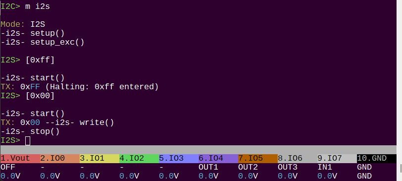
A new firmware branch i2s_mode has the framework for a new I2S mode. Nothing is implemented, but there is a playground to test things. I’m going to see if I can make the decoder screech a bit.
ETA: pushed an update with the I2S data out PIO installed. It makes crackling on my I2C amplifier, so I assume something is happening.
2 Likes
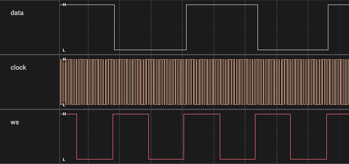
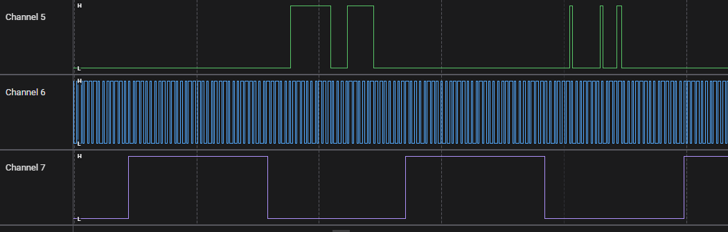
This is simply alternating periods of low and high (0x00000000, 0xffffffff). The signals look good. the data is high then low for left and right channels. Word Select (Left/right) is changing at ~44.1kHz.
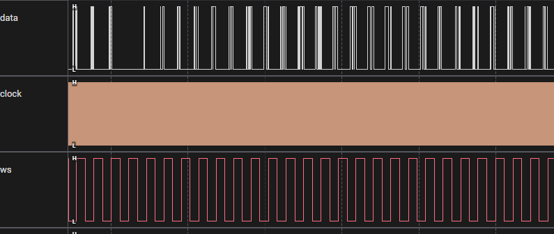
Stole a sine wave function from a random project and sent the output to the I2S bus.

We do indeed get a poorly formed sine wave in the auto output.
1 Like
    // 10 cycles of 1kHz at 44.1kHz = 10 * 44.1 = 441 samples
    #define TABLE_SIZE 441
    #define AMPLITUDE 32767.0  // Max amplitude for 16-bit signed
    #define CYCLES 10
    #define SAMPLE_RATE 44100
    #define FREQ 1000

    int16_t sine_table[TABLE_SIZE];

    for (int i = 0; i < TABLE_SIZE; i++) {
        // Each index represents: i / SAMPLE_RATE seconds
        // For 10 cycles: phase = 2*pi*FREQ*(i/SAMPLE_RATE)
        // But for exactly 10 cycles in 441 samples: phase = 2*pi*CYCLES*i/TABLE_SIZE
        double phase = 2.0 * M_PI * CYCLES * i / TABLE_SIZE;
        sine_table[i] = (int16_t)(AMPLITUDE * sin(phase));
    }

    for(int i=0; i<100; i++) {
        // Send the sine wave samples to the PIO
        // The PIO will handle the timing and output
        for(int j=0; j<TABLE_SIZE; j++) {
            // Send each sample, shift left to fit in 32 bits
            pio_sm_put_blocking(pio_config.pio, pio_config.sm, sine_table[j] << 16 | (sine_table[j] & 0xFFFF));
        }
    }
Calculate 1khz sine wave, 10 cycles so it’s smooth (44.1*10=441). It goes into a lookup table for speed, this could be DMAed for the best performance.
It is generally reliable. Occasionally the signal is a bit garbled.
Nifty to note: I2S uses signed values where 0 is the midpoint.
Next:
- Mode config option to set I2S frequency (and mono-stereo?)
sinecommand to output sine waves. Options to configure frequency. Some nifty math to calculate the right lookup table size and iterations for a smooth wave.- Handle incoming I2S, perhaps with a loopback function run by DMA (eg microphone to DAC).
2 Likes
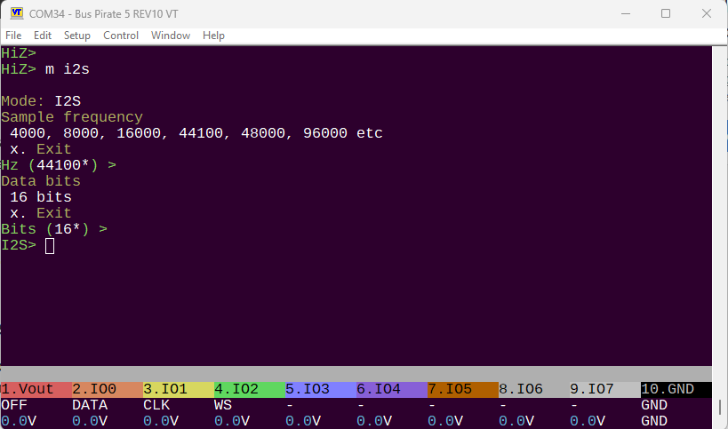
I2S mode configuration is working. Sample frequency 4K-96K, data bits is limited to 16 by the PIO.
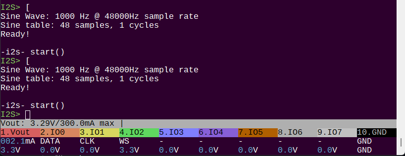
Still a bit of a hack, but [ is attached to a sine wave table generator. The table is customized for the current sample frequency. The sine wave freq is configurable, but that feature isn’t exposed yet.
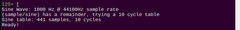
The very common audio CD sample rate of 44.1kHz does not divide equally (44100/1000 = 44.1 samples per cycle), so the sine wave is incomplete.
- The sine wave generator tests for a remainder (44100/1000 = 44.1).
- Then tests if a 10 cycle table also has a remainder ((44100/1000) * 10 = 441).
- If not, it generates a 10 cycle sine wave in the table, assuming it will fit.
- Max sine wave table is currently 500 samples.
This won’t be perfect for every combination of sample rate and sine wave frequency, but it will provide a useful range.
Working pretty solid now. The problems I heard before were due to my noise canceling headphones freaking out a bit at the volume.
This was an interesting and unexpected weekend project ![]() Maybe tomorrow I’ll have a look at the microphone.
Maybe tomorrow I’ll have a look at the microphone.
3 Likes
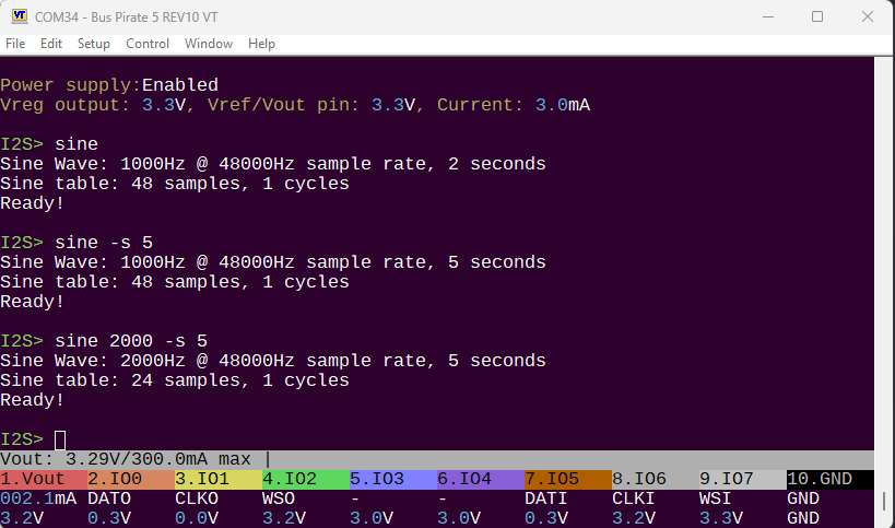
sine is now a command that accepts a frequency and duration options. Default is 1000Hz for 2 seconds.
Previously the wave fit test tried 1 and 10 cycles. Now it tries 1, and then 10 to 2 cycles. This will open up some previously unavailable frequencies.
Added an I2S input PIO program and attempted to sample from the INMP441 microphone and output on the UA1334A decoder. So far I only get static, but the waveform looks ok.
Pushed to the wrongly named i2c_mode branch of the repo ![]()
2 Likes
Looked at this a little bit. The data out from the mic is indeed being passed to the amp. I can see on a logic analyzer decode of the signal that the values going out are about 10 frames behind the incoming mic values.
The mic is 24 bits and the amp is currently being fed by a 16bit PIO program, so I’m chopping off the least significant bits. Maybe this is the wrong approach. To simplify I’ll implement a 24 bit output I2C program to match.
1 Like
Forgot to add a few notes:
- On the INMP441 breakout, despite the schematic all over the internet, there does not appear to be a pull-up or down resistor on the Left/Right channel pin. I’m holding it low with IO 4 and the
a 4command. - A pull-down is required on the data pin. The schematic shows one, it appears to be populated on the breakout, but it doesn’t actually seem to be doing that job. Added external 10K pull-down.
I tested sending 24bit frames to the amp instead of 16, but things really fell apart.
Also noticed I was shifting way too many bits when converting the 24 bit mic sample to 16 bit amp sample. Fixed that, but now the situation is worse. Before I could hear sounds when tapping the mic on the table or blowing into it, now it’s all just static.
Next step is probably to write my own PIO programs instead of depending on existing stuff. At this point I understand the protocols and that might be a better approach.
2 Likes

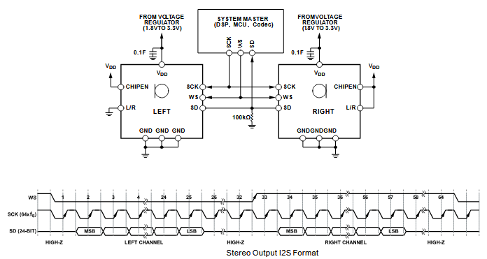
The I2S microphone PIO program from github changed the Left/Right clock on the rising edge of the bitclock.
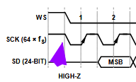
The datasheet shows the L/R clock changing on the falling edge of the bitclock.
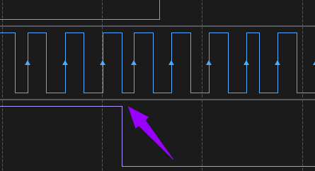
I wrote my own PIO program that more closely follows the datasheet. Now LR clock changes on the falling edge of bitclock.
I can hear something if I tap or blow into the microphone again, but it is mostly static. Not sure why this is so difficult, but next step will be rewriting the I2S output program.
1 Like
This has become a multiple weekend exploration lol.
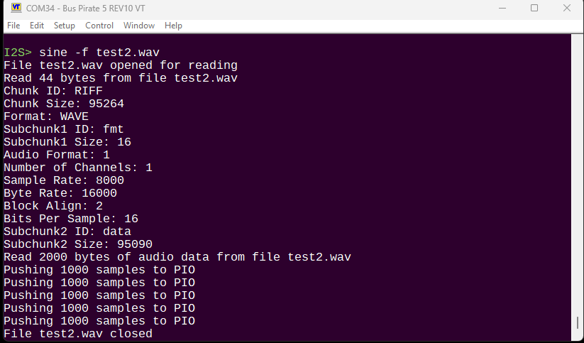
Still hung up on the microphone, so I wanted to make sure the amplifier is fully working. I hacked the sine command to parse a wav file header and play a few samples (1000) from the audio data. It does appear to work.
For this to be really effective we need to use the big buffer and load big chunks into a DMA ping pong buffer deal feeding the PIO.
Then maybe we can record from the microphone and see what the data actually looks like on a PC.
3 Likes
Installed an MP3 decoder to test this further, but it’s SUPER RAM heavy. Got it to compile and decode part of an MP3, but there’s a memory leak and it crashes. Given the huge fixed ram needs (12 to 15k?) plus stack memory (also heavy), it really doesn’t fit in the scope of the project. I’ll continue with small wav files.
2 Likes