I'm getting a I2C Bus Error when reading on a si7021

I’m duplicating the steps in the demo SHT21 Demo
I read the humidity fine. When I type to read the temperature, I type

[0x80 0xe0] [0x81 r:2]
And I get a bus error. Now what?

I2C START
TX: 0x80 ACK 0xE0 NACK (I2C bus error)
I2C>

I have the same error with the other steps (read serial #, read firmware revision). I added a delay (D:23) like the humidity, but that didn’t work

Thank you so much for the bug report. I’m going to reproduce this.

Does the (2) macro also get a bus error?

Bus Error is reported by the I2C module, and usually means the pins don’t match what it outputs. Common causes are lack of pull-ups or power supply on VREF/VOUT, but it sounds like the have that covered. It also happens when a device is still in write mode and doesn’t see the STOP condition, this hangs the bus.

I will pull my dev board and test.

I can confirm the exact same bug at the same place on all hardware versions with the current firmware, so it seems a bug worked its way into the I2C. I’m going to investigate further and will push a fix. My guess is we’re not sharing the RP2040 PIO well.

I tried several SI7021 (clones) and none of them ACK the E0 command. This is very strange. I’m going to dig further.

Do you know what part you’re using? My little breakout boards have four or five part numbers listed on the back with a “check box”, which is never actually checked. I had assumed they were compatible because of the shared 0x80 address and command sets. It turns out they’re similar but not totally compatible.

So, how to tell them apart?
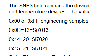
SI7021

image

image

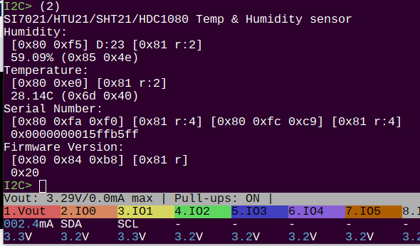
This is the SI7021 working properly with the built in macro.

imageimage

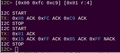
The key here is the first byte of the second half of the serial number. 0x15 indicates the part is SI7012.
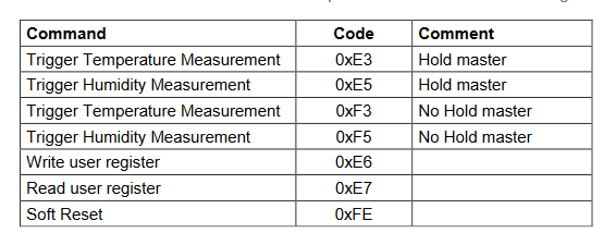
SHT21/HTU21

image

SHT21 and HTU21 are identical. They have mostly the same commands as SI7021, but they lack the 0xe0 read temperature after humidity command and firmware revision. The only way to tell them apart that I found is the engraved part number on the package.

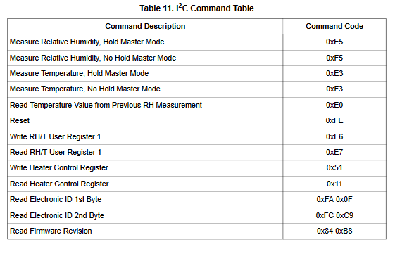
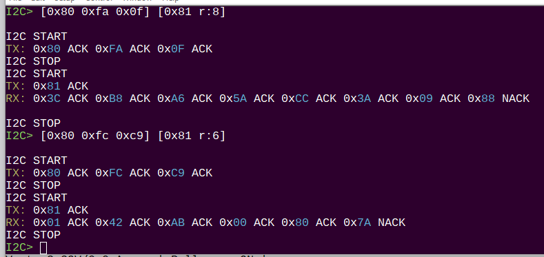
You have to dig into a different datasheet, but they also support the 0xfa 0x0f, and 0xfc 0xc9 serial number command. No mention of a manufacturer ID, but both the chips I have use 0x3c as first byte in first part of ID, and 0x01 as first byte of second part of ID.

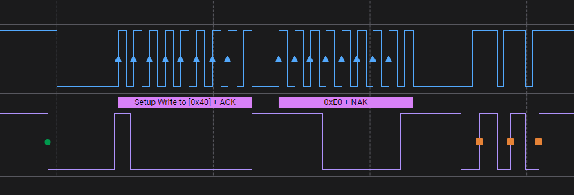
And here I notice the tutorial is wrong about reading the serial. The first command has 8 bytes with CRCs and the second had 6 bytes with CRC.

image

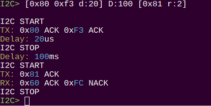
Instead of using the 0xE0 command to read temperature, use 0xf3. This is also supported by the SI7021. I had to increase the delay to 100ms despite what the datasheet says, and I added a recommended 20uS delay before the first stop condition.

The formula for calculating humidity and temperature are the same as SI7021.
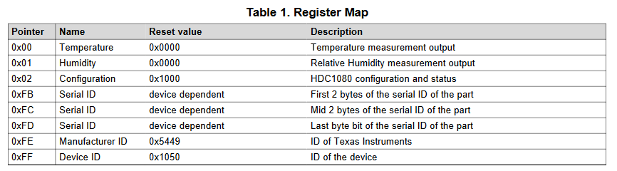
HDC1080

This is the HDC1080. It is actually made by TI, which shocked me to be honest.

image

The commands are significantly different. This is the temperature register.

image

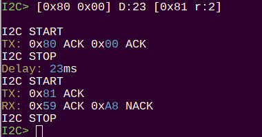
Command 0xff gets a 2 byte ID which is 0x10 0x50 for this part.

In light of this, I’m going to update the tutorial and macro to use the common commands of the SI7021 and SHT21D. I’ll remove reference to the HD1080.

Tutorial updated and new firmware pushed. Please let me know if this helps at all.

Ah hah! I was using a GY-213V-HTU21D board.
I issued the following commands - 2 of the 5 returns Bus Error


[0x80 0xf5] D:23 [0x81 r:2]
[0x80 0xf3] D:100 [0x81 r:2]
[0x80 0xfa 0xf0] [0x81 r:8] - Bus Error
[0x80 0xfc 0xc9] [0x81 r:6]
[0x80 0x84 0xb8] [0x81 r] - Bus Error

I’ll try again with the modified instructions and let you know.

2 Likes

[0x80 0xfa 0x0f] [0x81 r:8]

I think this might get it working.

[0x80 0x84 0xb8] [0x81 r] - Bus Error

This one isn’t supported by the SHT21.

1 Like

I noticed that when I run the SI7021/HTU21/SHT21/HDC1080 macro on my HTU21, and then imediately type the measure humidity command, I get a bus error. If I repeat the last command, it works

I2C> (2)
SI7021/HTU21/SHT21 Temp & Humidity sensor
Humidity:
[0x80 0xf5] D:23 [0x81 r:2]
32.03% (0x4d 0xe2)
Temperature:
[0x80 0xf3] D:100 [0x81 r:2]
22.73C (0x65 0x60)
Device not found
I2C> [0x80 0xf5] D:23 [0x81 r:2]

I2C START (I2C bus error)
I2C> [0x80 0xf5] D:23 [0x81 r:2]

I2C START
TX: 0x80 ACK 0xF5 ACK
I2C STOP
Delay: 23ms
I2C START
TX: 0x81 ACK
RX: 0x4F ACK 0xE2 NACK
I2C STOP
I2C>

After the SI7021/HTU21/SHT21 and getting the "Device not found error:, the next I2C command fails. If I run the SI7021/HTU21/SHT21 macro twice, or execute (2) and then (4), I get “Device not found.” But if I execute a bus command, it fixes this problem. Somehow the (2) macro fails, it leaves the BP in a broken state. If I execute a good bus command, it fixes this. If I execute [ ] I get an “I2C Bus Error” but it fixes the problem.

I2C> (1)
I2C address search:
0x72(0x39 W) 0x73(0x39 R)
0x80(0x40 W)
Found 3 addresses, 1 W/R pairs.
I2C> (2)
SI7021/HTU21/SHT21 Temp & Humidity sensor
Humidity:
[0x80 0xf5] D:23 [0x81 r:2]
29.43% (0x48 0x92)
Temperature:
[0x80 0xf3] D:100 [0x81 r:2]
21.81C (0x64 0x08)
Device not found
I2C> (2)
SI7021/HTU21/SHT21 Temp & Humidity sensor
Device not found
I2C> (4)
TSL2561 LUX sensor
Device not found
I2C> [ ]

I2C START (I2C bus error)
I2C> (4)
TSL2561 LUX sensor
ID: 5 REV: 0
Chan0: 117 Chan1: 43 LUX: 28

Hum, so htu21 doesn’t respond to the serial number command? I thought I saw it in the data sheet. I will look into this.

Were using a modified version of the I2C PIO app from the SDK. We have to split the read and write to different pins because of the buffer and the open drain bus. It reports any mismatch as a bus error. It’s right, but it’s really really strict and won’t work again until the bus recovers.

If I2C devices don’t respond with an ACK, instead of just moving on, we have to violently reset the bus with three stop conditions. The macro doesn’t do that, I should make it standard though and that part of the code (i2c device demos) desperately needs attention.

I’m planning to rewrite the PIO program to be a bit more flexible (but less parsimonious), I leveled up my skills working on the logic analyzer and have a decent grasp of it now.

That’s a bit rambling, but I guess there’s a few things

  • Macros need to recover from bus errors
  • Handling of bus errors needs to be more intuitive
  • PIO program needs to be rewritten so bus errors aren’t catastrophic

Is there any way to get more information than “I2C Bus Error?”

Sure, I will dig into that and finesse it a bit.

While writing the 2WIRE mode PIO program, I think I located the source of the I2C peripheral poor behaviour. The clock stretching feature lands it in error mode if there’s any unfinished transactions on the bus. This happens A LOT when first working with a new chip.

What I propose is to make clock stretching an option during I2C configuration. Then we load a PIO program with or without clock stretching. Something like this to drive the point home:

Clock Stretching Support?

  1. Disable (* Normal)
  2. Enable (Hard mode)
    (1)>

:slight_smile: I think this will be much more like the behavior everyone expects from an I2C peripheral.