Sourcing challenge: equivalents for expensive name brand parts:
TSOP4438 Vishay - Everlight IRM-3638J15. 0038 and 1838 seem to be common root part numbers
TSOP4456 Vishay - tsop34856 is around, but this part seems EOL. too bad, RX @ 45meters (?!)
QSE159 OnSemi - ugh, this one I need to talk to a few factories, seems rare
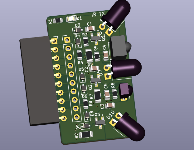
It seems like the 56kHz demodulator is not going to happen. Instead, I think dropping the LED size to 3mm, and using at least three might be a better plan. Ideally 1 tight beam in the center, flanked by two wider beams on the side/edges?
Can’t say I personally do much IR hacking, but I do love the idea of these expansion boards and would love to see more of them (both officially, and from the community). Especially with how easy it is to just put a basic pin header on the edge of the PCB – no need for a specialized connector or anything.
I’m glad you like the expansion boards, I’m going to keep making them as I build out the firmware. It’s helpful for me to have a solid platform for testing multiple chips.
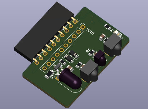
This is probably where it’s headed. 3 x 3mm 100mA IR LEDs, each with a constant current driver. I’m going to use good Vishay high power IR LEDs - no reason to cheap out there.
I should mention that (IMH)) having the ability to store and load “scripts” will become more important. For instance, the setup for the SLE4443/SIM had several steps that wasn’t obvious to a new user (i.e. me). The Github repository can contain several “example” scripts that would be very helpful to new users - a component library so to speak. They should be eventually be added to the Device Demos but we all know keeping documentation in sync with the source is always a challenge, An IR database would certainly need this as well.
As for adapter boards, having a general purpose prototype board could be another item to add to the store.
However, I think we can use less current and add an additional LED if we use two LEDs per current driver. At the moment a lot of excess current is burning off in the transistors. It depends if we have enough voltage overhead. I’ll look into it soon, but for now I’m sending this board off for prototypes.
Yeah, I didn’t go any further with the IRDA. It seems to be dated, though it might be useful for vintage stuff.
I like having a look at IR signals though, and it’s nice to be able to copy weird cheap remotes (LED strips for example). And of course TV B Gone functionality.
At some point we’ll need to look into offline functionality. At the moment the button doesn’t do anything until the terminal has been enabled. There’s no reason it has to be like that, its just where the interrupt flag is serviced in the main loop. After that it would use the built in scripting stuff.
I’m sure you could start some kind of timer on the first button interrupt to do double/triple taps.
I have one button on a piece of kit for job and it has way more than 3 functions. Ok there is a beeper so you get feedback. Bit BP5 has lots of LEDs.
In my case push and hold for 10 seconds puts you in shift mode1, hold for 20 shift mode 2. I have 3 LEDs so use them to show one of 8 options. (well 6 as initial value and final value are backout/null)
Just looking at bus pirate and we have 10 leds on the top. Hold button down, after a few seconds all LEDs out then each second light a further LED. 1 to 10 for button1.scr … button10.scr. Hold until all go out again for cancel.
We do also have an LCD, but I get that it is a much bigger pain in the rear to use that. Paul, who did the scope, mentioned that there are some nice graphics libraries and I hope to look into that some day too.
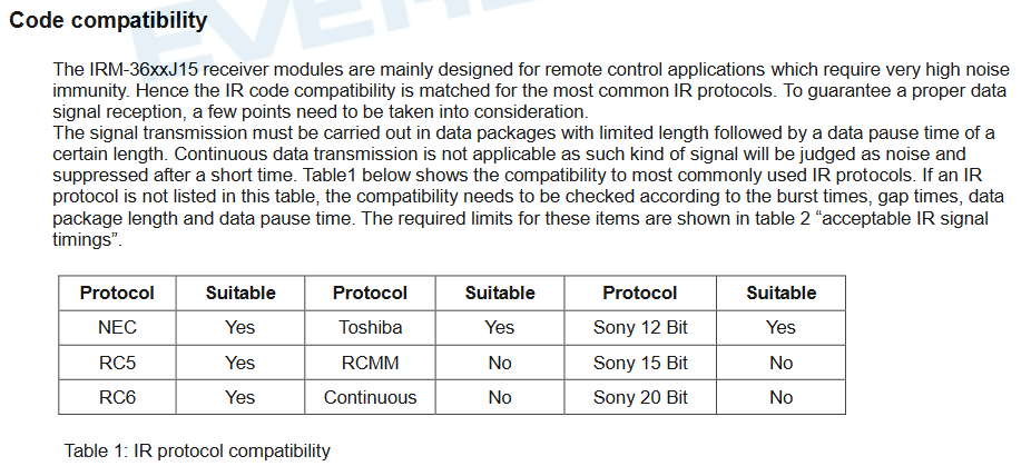
IRM-3638T is a bit older, bit more expensive, uses a bit more power. However I think it may work with a wider range of remotes because it is less highly optimized.
IRM-3638J15 Seems to be the most recent revision. Cheaper. Lower power. +1 extra meter range. Highly optimized against modern sources of interference (energy saver bulbs, TFTs). Might not work with some less common remote protocols (this is to be determined, just a cursory look):
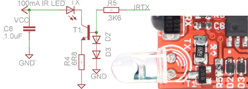
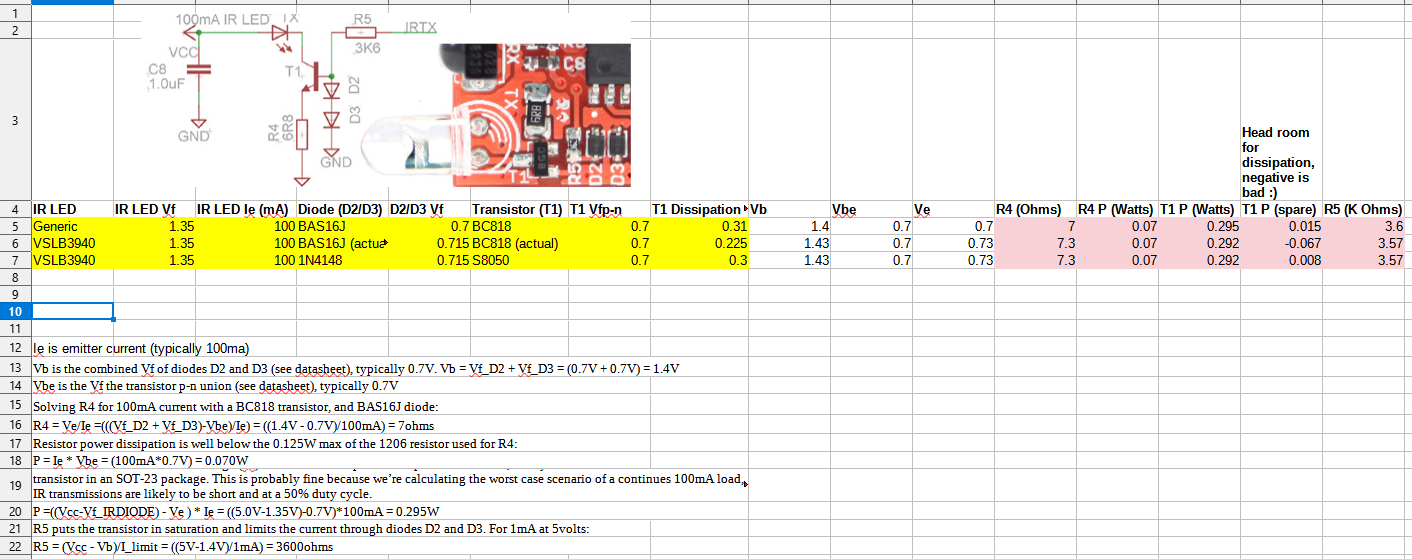
In the constant current driver design the transistor (T1) collector current (LED side) is equal to emitter current (R4 side). The current is set by R4:
Emitter current Ie = (Ve-0) / R4
Ve = Vb - Vbe = (1.4V - 0.7V) = 0.7V
Vb is the combined Vf of diodes D2 and D3 (see datasheet), typically 0.7V. Vb = Vf_D2 + Vf_D3 = (0.7V + 0.7V) = 1.4V
Vbe is the Vf the transistor p-n union (see datasheet), typically 0.7V
Solving R4 for 100mA current with a BC818 transistor, and BAS16J diode:
Resistor power dissipation is well below the 0.125W max of the 1206 resistor used for R4:
P = Ie * Vbe = (100mA*0.7V) = 0.070W
On the down side we transferred a lot of the current from the resistor to the transistor. The transistor in IR Toy v2 can potentially run hotter than the transistor in v1.
For an IR LED with a forward voltage (Vf) of 1.35 volts the power dissipation is 0.295W, nearly the rated 0.310W of the BC818 transistor in an SOT-23 package. This is probably fine because we’re calculating the worst case scenario of a continues 100mA load, IR transmissions are likely to be short and at a 50% duty cycle.
P =((Vcc-Vf_IRDIODE) - Ve ) * Ie = ((5.0V-1.35V)-0.7V)*100mA = 0.295W
RX puts the transistor in saturation and limits the current through diodes D2 and D3. For 1mA at 5volts:
These calculations are also in a spreadsheet in the hardware folder of the project archive. Special thanks to Rafa and rsdio who helped with the constant current circuit.
Finally ordered parts for this, we’re a few weeks behind :<
The IR TX driver transistors and diodes need to be updated after testing the basic design (use newer, cheaper, more common/available parts). Here’s the math from the USB IR Toy V2, which I will put into a spreadsheet.
It seems like a better approach is to use 2 LEDs in series with 2 drivers = 4 LEDs per board. or 3 LEDs in series with a single driver or 2 drivers with 3 series LEDs each. That burns off the extra power in the LEDs instead of the NPN, keeping us in spec, lowering part counts, and saving power.
Looking at side emitters instead of through hole leds, seems simpler for assembly.
For IR analysis, allow me to recommend reaching out to the kind gentleman at AnalysIR.com. I’ve used both his hardware and software for over a decade. His knowledge is top-notch, and he even added some custom protocols for me (one of the Lego devices, not mindstorm).
He may also be interested in helping enabling the BP5 to be another source of data usable in his AnalysIR application, which is truly outstanding.
Finally, he has a nice kit of “starter” IR receivers that covers all four common IR frequencies, and for $15 you get a nice assortment to test out in your target environments. Note the need for one part to get the IR frequency … and how many of the parts will reject long IR signals (air conditioning unit remotes are notorious for having this problem, for example).
I have no relationship with AnalysIR except as a satisfied customer, and they have no idea I’m still pointing folks their way; This is just my personal opinion and experience, of course, but … maybe worth looking into?