Infrared IO "explorer"


Vishay TSMP98000 (yellow) vs Opti-Fake OS1200MW-A1 (blue). The Chinese domestic part has much cleaner edges. It’s a rainy day in amsterdam, so I can’t test spurious spikes from the sun, etc, which may be Vishay’s strong point.

Vishay TSSP4038 (yellow) vs Everlight IRM-3638T (blue). Both seem ok. To me the Everlight has more even high and low bits.

There’s 3 models of 38kHz demodulators to check, and then I need to re-source the 56kHz demodulator, there are cheaper/more available parts from Vishay.

2 Likes

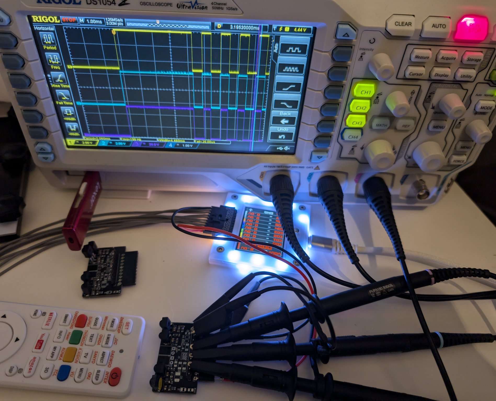
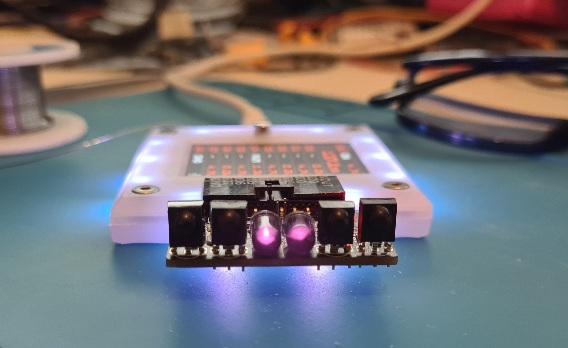
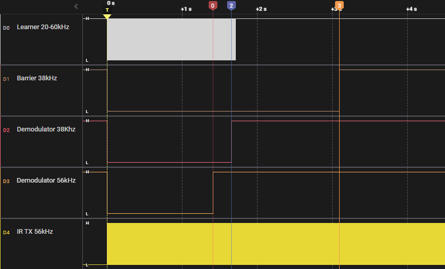
First time using the third scope channel. I’m both proud and embarrassed.

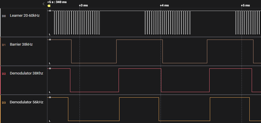
First up, just a small re-test of Vishay TSMP98000 (yellow) vs Opti-Fake OS1200MW-A1 (blue). Opti-fake specifies 10K pull-up, like all the other sensors we’re reviewing. However the Vishay specs 4.7K. In the first test both had a 4.7K resistor because we might pick and place a single run of PCBs, then hand place different sensors. A budget board with cheap sensors and a HQ board with Vishay sensors. That doesn’t really seem necessary at this point.

The opti-fake worked just as well with a 10K pull-up, so we can eliminate one BOM line.

Some interesting comments from Mastodon: maybe the cheap Chinese part is performing better because it is a more recent design and CMOS process. The Vishay parts have been around for ages and the die may be an older process that doesn’t have as sharp edges.

Next up are Vishay TSOP34438 (yellow - 8元), Everlight (also made in Taipei) IRM-3638J7(blue - 1.6元), and Opti-fake OS-883YM-MS (red - 1.2元). No major performance difference here. Everlight has a bit of noise in the highs, while both Vishay and Opti-fake have noise in the lows.

Its cloudy and windy, so no spurious signal check today.

Sensor Brand Part C R Pull-up
Barrier (38kHz) Everlight IRM-3638J7 4.7uF 100R 10K
Learner (20 → 60kHz) Opti-fake OS1200MW-A1 4.7uF 100R 10K
38kHz (36-40kHz effective) Opti-fake OS-883YM-MS 4.7uF 100R 10K
56kHz ? ?

This looks like the guest list.

56kHz

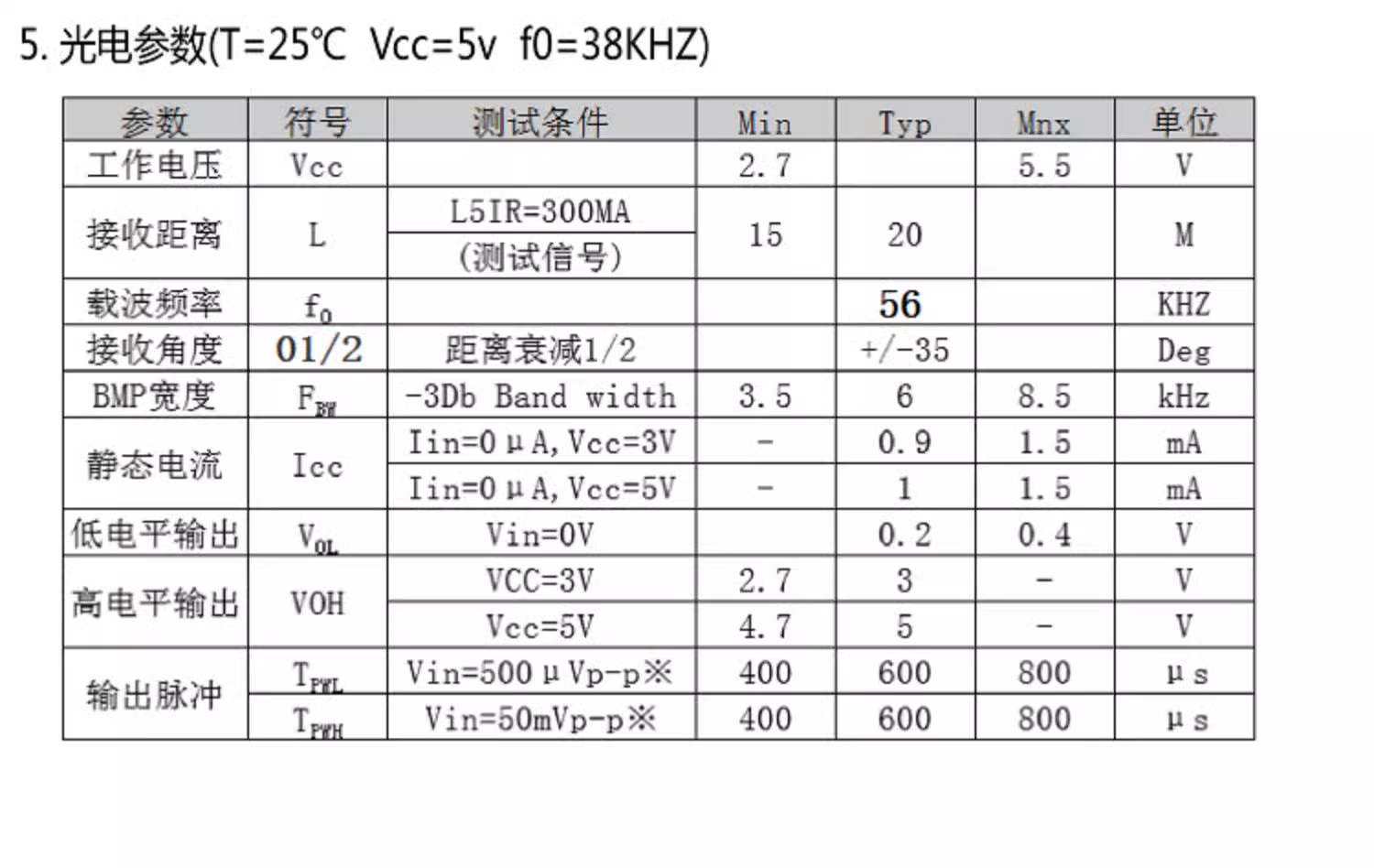
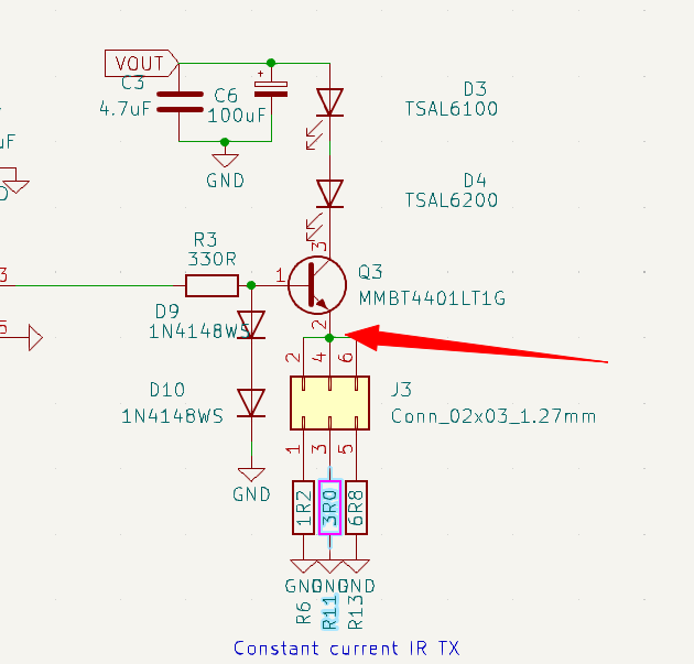
One last part to source. The 56kHz demodulator. 56kHz isn’t that common, but it won’t be picked up by the 38kHz sensor and our collection should be as complete as possible.

image

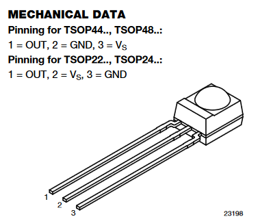
The kit of sensors from AnalyzIR came with a TSOP2256. The catch is that TSOP22xx series have a different pinout so they don’t fit in the PCB for real-world testing.

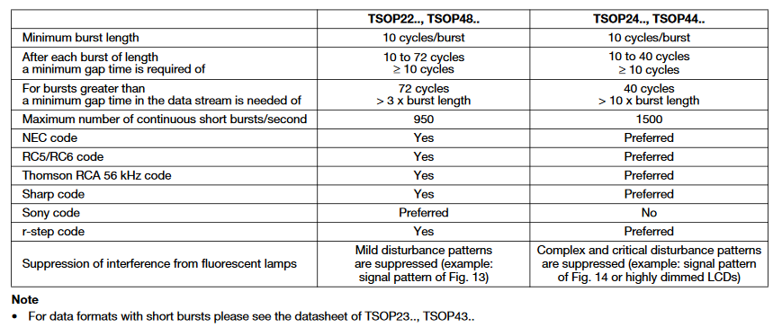
TSOP2256 has auto gain control of 2. Here’s the specs. I’ll try to source something from Vishay, and contact opti-fake to see if they have a 56kHz part.

Remotes

Two universal remotes with 5 day shipping were like $5 on AliExpress. I opened both, from different manufacturers, and they’re just a single unmarked 16 pin SOP chip, an LED and an IR LED.

Edit

Looks like I swapped the IRM-3638T and IRM-3638J7 in my posts.

3 Likes

Finally, finally, finally found a 56kHz demodulator. At least maybe. The part number ends in 38 (as in 38khz), datasheet says 38khz everywhere except one place where “56” has been pasted over.

The supplier is actually an IR stuff (die bonding) factory, and it sure seems like they’re custom manufacturing these for us over the weekend.

I’ll defo be testing these to make sure they’re actually 56kHz. There’s no other info about automatic gain control, or what pulse widths are rejected. The supplier did say they are not barrier style (continuously on), so they have some kind of signal rejection.

The main thing is that we now have 4 sensors covering all common IR frequencies. I hope.

2 Likes

20240731_164732

The (hopefully) final IR Toy plank arrived yesterday.

Transmitters

LED Angle Output Current Brand Part
Narrow angle +/-10 degrees 940nm infrared 100mA-1.5A* Vishay TSAL6100
Medium angle +/-17 degrees 940nm infrared 100mA-1.5A* Vishay TSAL6200

* 200mA at 50% duty cycle with pulse time < 100uS

The infrared transmitter has a constant current driver and two genuine Vishay LEDs.

  • TSAL6100 is a narrow beam LED, for long distance focused transmission.
  • TSAL6200 has a moderately wider beam that will cover a larger area, but at a shorter distance.
  • A +/-25 degree TSAL6400 wide beam version is also available, but the experts at AnalysIR recommended 6100 and 6200 as the best pairing.

Output currents of 100mA, 200mA and 300mA are selected with the jumper at the center of the PCB. The LEDs are rated for 100mA constant current output. Higher currents are possible, but must be a pulse modulated signal (PWM) with less than 50% duty cycle or the LEDs may be damaged.

Receivers

Sensor Frequency Brand Part C R Pull-up
Learner 20-60kHz Os-opto OS1200MW-A1 4.7uF 100R 10K
Barrier 38kHz Everlight IRM-3638J7 4.7uF 100R 10K
38kHz demodulator 36-40kHz Everlight IRM-3638T 4.7uF 100R 10K
56kHz demodulator 56kHz CHQ CHQ0038L-56kHz 4.7uF 100R 20K

Here’s the sensor line up. I tested everything I could get my hands on, an these seem great for lab use and are more affordable/available than Vishay parts. CHQ did a special manufacturing run of the uncommon 56kHz demodulator for us over a weekend.

Here’s what it looks like when we hit the sensors with an IR remote control from close range.

  • Learner - Passes through true, modulated signals in the range 20kHz to 60kHz. Lower and higher frequencies should be filtered out, creating less false readings. This is called a “learner” because it is used in universal remote controls to copy/learn other remote signals.
  • Barrier - Demodulates an IR signal to high and low. When IR light modulated in the range of 36-40kHz hits the sensor, it outputs low. The learner is passing the modulated signal (lots of up and down). The barrier, and other demodulators, convert those bursts to high and low. Barrier sensors are used to detect a break in a beam of light for door sensors, soap dispensers, automatic faucets and in automated production line equipment. This sensor is centered at 38kHz, but is 90% effective in the common 36-40kHz range.
  • 38kHz demodulator - Unlike the barrier type demodulator, this sensor attempts to filter out unwanted signals that don’t resemble a remote control protocol. It has a minimum and maximum burst timeout, as well as automatic gain control. Various models are available with filter settings that match specific remote control protocols to maximize reception range in TVs and other IR remote controlled appliances. This sensor is centered at 38kHz, but is 90% effective in the common 36-40kHz range.
  • 56kHz demodulator - Similar to the 38kHz demodualtor, but centered in the very uncommonly used 56kHz range. Most vendors don’t want to sell us these parts because they’re obsolete. We eventually found a factory that could make a small custom batch. It’s not strictly needed, but we want the board to cover all the bases. Also, it just looks cool to have 4 sensors and 2 LEDs.

Let’s take a look at the timeout embedded in each sensor.

  • W 5 - enable a 5 volt power supply
  • G - setup PWM ouput, choose IO4 for the IR Toy infrared LED transmit pin
  • Set 38kHz output at 50% duty cycle

The bottom trace shows the Infrared Transmit LED PWM at 38kHz. The IR LEDs are transmitting a 38kHz modulated signal.

  • Leaner - passes the modulated 38kHz signal through, matching the highs and lows of the transmitted signal. This version times out after about 1.5 seconds, but other versions will pass the signal indefinitely.
  • Barrier - stays low for as long as the 38kHz modulated signal is applied.
  • 38kHz demodulator - after about 2 seconds it times out and, probably, internally adjusts the gain in an attempt to filter out the ongoing “noise”.
  • 56kHz - Wait, shouldn’t this sensor filter out the 38kHz modulated signal? Yes and no. If the signal source is a significant distance away, the 56kHz would be significantly less sensitive than the 38kHz sensors. On the test bench though, the 38kHz signal bounces off near objects and is powerful enough to activate the 56kHz sensor too.

We see the same with a 56kHz signal too. Both 38kHz centered sensors respond to the 56kHz signal when it is powerful and nearby, but notice at 3 seconds (marker 3) the barrier sensor also goes high.

This is because I moved the IR board to point at a distant wall instead of nearby objects. When the signal has to travel a few meters, the 38kHz barrier sensor is no longer sensitive enough to detect it.

2 Likes

It is work such as this that makes me confident in purchasing your designs, Ian. Thank you for verifying the behavior, and even more for sharing your work. :two_hearts:

3 Likes

image

There is a new infrared branch with INFRARED mode. It currently uses the pico SDK IR NEC transmit PIO programs to transmit 8 bit address + 8 bit data payloads.

At the moment this is only for checking that the current settings are correct with a scope, but will expand eventually.

1 Like

Quick transmit current check. Using Ohm’s law we should be able to calculate the current by measuring the voltage at the current limiting resistor. In theory it should be ~70mA/160mA/400mA.

6.8ohm resistor with 1.8volt peak = 263mA (!!)

3.0ohm resistor with 1.23v peak = 413mA (!!!)

1.2ohm resistor with 0.624v peak = 533mA (!!!)

Not sure if I’m misunderstanding, or my scope is setup incorrectly. There is going to be variation due to components and tolerance, but something seems off here.

1 Like

So, it occurred to check if the diodes were giving the correct (1.2-1.4volt) offset on the transistor base. They were not. SOD-323 is such an annoying package. Hit it with flux and resoldered the diodes.

There we go, that’s the transistor base at 1.4volts.

0.65volts @ 6.8ohm = 95mA

0.62 @ 3ohms = 206mA

0.47 @ 1.2ohms = 391mA

I’m satisfied with this. I was shooting for a range from “safe to always be on” to “as much as possible”.

2 Likes

Only tangentially related: What process are you using to get screen grabs from your DS1054? I love mine, but I’ve struggled when attempting to use it over the network. You have so many captures! Would love to know if it’s a great software using the network interface, or other?

2 Likes

USB flash drive in the front port, hit the storage button and follow the awkward menu prompts. It works but it feels cheap and not well dog-fooded

1 Like

I haven’t tried any of them, but there are a few ways it can be done. Try these solutions;

https://www.envox.eu/studio/studio-introduction/

^ Here’s a contribution from a friend. Let us know how it turns out.

2 Likes

Second hackaday link got me to a github issue where the minimal solution was found:

Get image of what’s onscreen:

echo ":DISPLAY:DATA? ON,OFF,PNG" | nc -w1 192.168.1.24 5555 | dd bs=1 skip=11 of=captures/DS1104Z_$(date '+%Y-%m-%d_%H.%M.%S').png

Get CSV data for channel 1:

echo ":WAV:SOUR CHAN1
:WAV:MODE NORM
:WAV:FORM ASCii
:WAV:DATA?" | nc -w1 192.168.1.24 5555 > captures/DS1104Z_$(date '+%Y-%m-%d_%H.%M.%S')_channel1.csv

No software installation required, and makes it easy (with review of the DS1054Z manual) to alter / derive other commands. :tada:

3 Likes

@henrygab Thanks for the feedback! I will be sure to pass this on to a few individuals i know with the same scope.

2 Likes

This board will be at the office tomorrow. I pushed a firmware with a basic IR mode and a test command for production testing the boards.

The test procedure:

  • Test each sensor has a pull-up (IO high)
  • Transmit a NEC5 dataframe (0xff 0xff) and test that each sensor goes low
1 Like

Any idea when this will be available?

1 Like

I want to make the next three planks available at once, currently we are waiting on Programming Voltage SMPS, which should be done today or Monday.

3 Likes

Any updates on availability of the the 3 new planks?

1 Like

All tested and ready to go :slight_smile: they’re at the photographer at the moment. Then we’ll pop them in the store.

3 Likes

Pics or it didn’t happen. :stuck_out_tongue_winking_eye:
I’ll be off work all day tomorrow just hitting refresh on the site to get mine on the way asap! :upside_down_face:

2 Likes

My grant expires tomorrow. I genuinely hope that these planks arrive in the store in time.

2 Likes