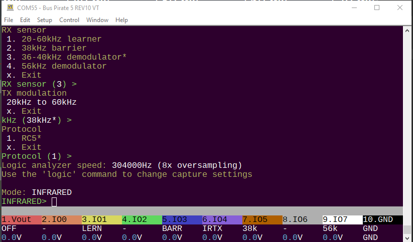
I’m going to flesh out IR Toy support. Here’s the main binary functions of the IR Toy V2:
Infrared mode now has configuration options:
- The receiving sensor to decode
- Transmit modulation speed
- Protocol (currently only NEC supported)
RC5 packets are 16 bits: 8 bit address, 8 bit data. Send it as a 16 bit number.
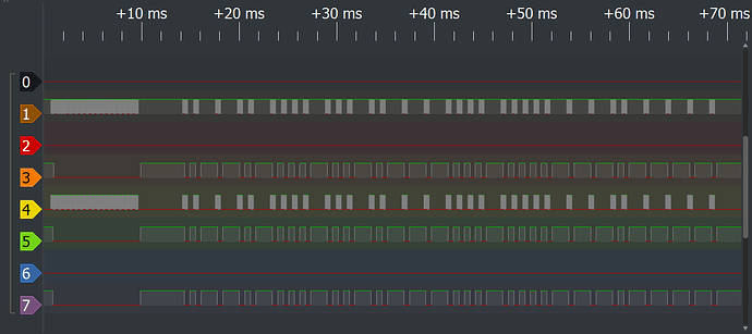
It works with FALA. IO4 is transmitting the NEC code. The learner on IO1 passes the modulated signal directly. The demodulators, well they demodulate it - even the 56kHz sensor because it is such close range.
Next lets see if we can get decoding to work.
Receive is working ![]() Note:
Note:
- Transmit and receive are currently fixed at 38kHz, the config setting is not honored
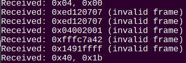
RC5 frames are checked for valid data. If a frame is invalid, it will be noted.
Well this is interesting. I have this cheap universal remote for testing. It claims to control multiple brands under the default setting.
It seems the way it does this is by blasting out a bunch of codes every button press. Just flooding the zone ![]()
Since it is a holiday, I might do something fun like port the TVBGone instead of getting further into the weeds on the mode.
I was wrong about the protocol, we currently support NEC.
This should do the trick for RC5 though. More docs.
There is a new branch with the addition of RC5 (well, the basis of what could become RC5).
Issue: after fixing some bugs in INFRARED mode, the Bus Pirate will no longer connect to my computer. TeraTerm freezes/crashes and once my computer lost mouse. Crazy stuff.
I want to roll back to a previous version to compare, but now every download is seen by windows as a trojan ![]()
bus_pirate5_rev10-freezes.zip (242.9 KB)
Does this lock up anybody’s Bus Pirate 5? If so, we may be onto the cause of the other user’s connection issues. It’s really strange though, I only changed stuff in infrared mode. Maybe my computer is just messed up?
Further investigation
- Firmware isn’t causing the connection issues, it works on other bus pirates
- infrared mode freezing fixed with same fix as led mode apparently. When switching between two submodes of a mode, the init gets overridden and the deinit fails catastrophically when trying to unload the wrong PIO program.
- RC5 mode exists, but doesn’t seem to twiddle pins yet.
- thinking the connection issue may be a windows saved driver issue, I cleared all existing COM ports and loaded the manufacturing firmware without individual serial numbers in the USB descriptor. The freezing bus pirate still doesn’t connect
Next I’ll run it under debug and see if I can spot where things are going wrong.
Are there circumstances where an exception/reading or writing to the wrong address range would damage the chip? Perhaps the hardware? Or maybe it’s ESD damage to the USB peripheral?
It is loading the config file. LEDs are good. LCD is active and shows voltages applied to the pins. But when I try to connect teraterm freezes up until I remove the bus pirate.
Just one thing springs to mind:
IF you’ve added debug output, make sure you’re not sending it from Core1. (Core1 will deadlock trying to print debug output if the output buffer is full.)
Some demo code for Manchester encoding/decoding.
Pins are moving ![]()
Yeah! We receive what we transmit.
Next steps:
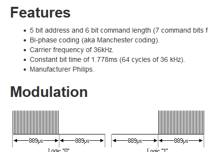
- Get the bit period right (1.778ms)
- Apply a carrier frequency (ideally chosen by the user)
The NEC protocol uses two PIO programs for the carrier frequency: one to generate the PWM, the other to output the bits. I’ll study that first.
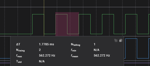
Seem to have the right bit duration now.
Does anyone know the “right” way to calculate this? I did as follows, but I don’t think that’s the right way to do it on the chip:
- 1778us per bit (1.778ms)
- 12 ticks per bit (from PIO program)
- 1778us/12 ticks per bit = 148.16 us per tick
- 0.008us per clock (at 125MHz clock)
- 148.12us per tick / 0.008us per clock = 18520.833 clocks per tick at 1778us
It looks like that simplifies to:
(Btime*MHzclock)/Ticks per bit
That still seems like some big and tiny numbers ![]()
; NO SIDE SET for max delay values
; count pulses a bit better, what to do about the 3 extra clock on each bit?
.wrap_target
do_1:
    set y, 62           [28]     ; Set Y to 31 (32 pulses)
bit_1_loop:
    ;pins 0 [31]      ; Set pin low for 32 cycles (1 delay, +1 for nop)
    jmp y-- bit_1_loop [31]      ; Loop until 32 pulses are sent
    set y, 31                ; Set Y to 31 (32 pulses)
bit_1_loop_2:
    pins 1 [31]   ; High for 32 cycles (1 delay, +1 for nop)
    pins 0 [30]   ; Low for 32 cycles (1 delay, +1 for nop)
    jmp y-- bit_1_loop_2     ; Loop until 32 pulses are sent
    jmp get_bit              ; Get the next bit
do_0:
    set y, 31                ; Set Y to 31 (32 pulses)
bit_0_loop:
    pins 1 [31]   ; High for 2 cycles (1 delay, +1 for nop)
    pins 0 [30]   ; Low for 2 cycles (1 delay, +1 for nop)
    jmp y-- bit_0_loop       ; Loop until 32 pulses are sent
    set y, 63                ; Set Y to 31 (32 pulses)
bit_0_loop_2:
    ;pins 0 [30]   ; Low for 2 cycles (1 delay, +1 for nop)
    jmp y-- bit_0_loop_2 [31]     ; Loop until 32 pulses are sent
public start:
get_bit:
    out x, 1                 ; Always shift out one bit from OSR to X, so we can
    jmp !x do_0              ; branch on it. Autopull refills the OSR when empty.
.wrap
A draft concept of RC5 transmitter. It’s pretty brute force. The NEC PIO program uses a carrier generator in on SM and a control program in a second SM. They use interrupts to trigger the pulses. As far as I can tell, that means both SM have to be marching in lock step and I don’t want to battle timing that badly.
The idea is to use big delays with a fast clock to the get_bit and y register reload.
I believe that I can cut this in half by jumping on x and combining the “burst” and “quiet” into reusable code. Then correct the timing with delay on the jump instructions. I need to think it over a bit though.
Edit: another possibility is to use two programs, one that generates a carrier frequency on the pin. The other switches the pin direction to enable/disable. This is probably the better solution?
.wrap_target
do_off:
    set y, 62           [28]     ; make up for 3 used cycles
off_loop:
    jmp y-- off_loop [31]      ; Loop until 32 pulses are sent
    jmp !x get_bit             ; Get the next bit
do_on:
    set y, 31                ; Set Y to 31 (32 pulses)
on_loop:
    pins 1 [31]   ; High for 32 cycles (1 delay, +1 for nop)
    pins 0 [30]   ; Low for 32 cycles (1 delay, +1 for nop)
    jmp y-- on_loop     ; Loop until 32 pulses are sent
    jmp !x  do_off              ; Get the next bit
public start:
get_bit:
    out x, 1                 ; Always shift out one bit from OSR to X, so we can
    jmp !x do_on              ; branch on it. Autopull refills the OSR when empty.
.wrap
Simplified. The timing is still a bit wonky.
Ideally the RC5 bit period is 1.776, and I think we got really close. RC5 transmitting works, in theory (if the PIO pull/push is set to 14bits).
.wrap_target
    set X, (NUM_CYCLES - 1)         ; initialize the loop counter
    wait 1 irq BURST_IRQ            ; wait for the IRQ then clear it
cycle_loop:
    set pins, 1 [1]               ; set the pin high (2 cycle)
    set pins, 0                  ; set the pin low (1 + 1 cycles)
    jmp X--, cycle_loop
.wrap
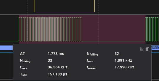
I tried several methods to generate the carrier and data. Using two programs ended up being the best option after I got the timing figured out. This part generates 32 cycles of 36kHz carrier frequency.
.wrap_target
do_1:
    nop [7]                 ; low 6 cycles
    irq BURST_IRQ [4]       ; high 6 cycles (1 + 2 + 1 + 2 = 6 cycles high)
    jmp get_bit             ;
do_0:
    irq BURST_IRQ [7]       ; high 6 cycles
    nop [5]                 ; low 6 cycles (1 + 3 + 2 = 6 cycles low)
public start:
get_bit:
    out x, 1               ; Always shift out one bit from OSR to X, so we can
    jmp !x do_0            ; branch on it. Autopull refills the OSR when empty.
.wrap
Then this little guy just sleeps and throws an interrupt to the first program when a burst is needed.

Receiving still needs some work. This is actually inverted from what we sent because the IR demodulator inverts the signal. I tried to use gpio_inover to invert it at the GPIO pin, but the PIO didn’t agree to see it that way.
The other issue is that RC5’s start bit is a 1, so the sensor misses the first half of the bit.
start_of_0:            ; We are 0.25 bits into a 0 - signal is high
    wait 0 pin 0       ; Wait for the 1->0 transition - at this point we are 0.5 into the bit
    in y, 1 [13]        ; Emit a 0, sleep 3/4 of a bit
    jmp pin start_of_0 ; If signal is 1 again, it's another 0 bit, otherwise it's a 1

.wrap_target
start_of_1:            ; We are 0.25 bits into a 1 - signal is 1
    wait 1 pin 0       ; Wait for the 0->1 transition - at this point we are 0.5 into the bit
    in x, 1 [13]        ; Emit a 1, sleep 3/4 of a bit
    jmp pin start_of_0 ; If signal is 0 again, it's another 1 bit otherwise it's a 0
.wrap
The current manchester decoding program is simple and assumes a start bit of 0 (high-low), it is unaware of the first half bit or how much data we expect (14 bits).
The X and Y scratch registers are currently holding a 1 and a 0 to push into the shift register. We need one of those free to count our 14 bits and then prepare for the next (half) start bit.
in y, 1 [13] ; Emit a 0, sleep 3/4 of a bit
We can’t put a 1 or 0 directly into the shift register, but we can use NULL to get a zero which is half a good.
in NULL, 1 [13] ; Emit a 0, sleep 3/4 of a bit
I believe we can do this and reclaim the Y scratch register for counting the bits, giving us a way to track the half start bits.
EDIT:
    wait 1 pin 0       ; Wait for the 0->1 transition - at this point we are 0.5 into the bit
    in x, 1 [13]        ; Emit a 1, sleep 3/4 of a bit
We can probably be sneaky and reclaim the X register as well.
    wait 1 pin 0       ; Wait for the 0->1 transition - at this point we are 0.5 into the bit
    in pins, 1 [13]        ; Emit a 1, sleep 3/4 of a bit
We’re already waiting for the pin to go to 1, so we could just use the pin itself as a source of one-ie goodness.
public start_of_half_bit:
    set y 31
    wait 0 pin 0 [2]   ; Wait for the 1->0 transition - this is the middle of the start bit
    in x, 1 [3]        ; Emit a 1, sleep 1/2 of a bit

.wrap_target
check_end:
    jmp y-- start_of_half_bit ; end of 14 bits
    jmp pin start_of_1 ; If signal is 1 again, it's another 1 bit, otherwise it's a 0 (inverted)
start_of_0:            ; We are 0.25 bits into a 0 - signal is high
    wait 1 pin 0       ; Wait for the 0->1 transition - at this point we are 0.5 into the bit (inverted)
    in null, 1 [11]    ; Emit a 0, sleep 3/4 of a bit
    jmp check_end
start_of_1:            ; We are 0.25 bits into a 1 - signal is 1
    wait 0 pin 0       ; Wait for the 1->0 transition - at this point we are 0.5 into the bit (inverted)
    in x, 1 [12]       ; Emit a 1, sleep 3/4 of a bit
.wrap
I believe this will do it. ASM can be confusing ![]()
Oh man, that was a nasty one and it turned out to be dead simple.
public entry_point:
    set y (NUM_BITS-1)  ; initialize the bit counter, with some delay to avoid triggering on previous bit
    wait 0 pin 0       ; Wait for the 1->0 transition - this is the middle of the start bit
    in x, 1 [6]        ; Emit a 1, sleep 1/2 of a bit

.wrap_target
check_end:
    jmp y-- next_bit ; end of 14 bits
    jmp entry_point  ; end of 32 bits
next_bit:
    jmp pin start_of_1 ; If signal is 1 again, it's another 1 bit, otherwise it's a 0 (inverted)
start_of_0:            ; We are 0.25 bits into a 0 - signal is high
    wait 1 pin 0       ; Wait for the 0->1 transition - at this point we are 0.5 into the bit (inverted)
    in null, 1 [11]    ; Emit a 0, sleep 3/4 of a bit
    jmp check_end
start_of_1:            ; We are 0.25 bits into a 1 - signal is 1
    wait 0 pin 0       ; Wait for the 1->0 transition - at this point we are 0.5 into the bit (inverted)
    in x, 1 [12]       ; Emit a 1, sleep 3/4 of a bit
.wrap
So I was jumping wrong on the y-- and it got stuck in the entry point giving only ones. I was sharp enough to catch that right away.
Next I just couldn’t get the data right. It was always garbled.
Remember this from yesterday? RC5 always starts with a half start bit “1”.
public entry_point:
    set y (NUM_BITS-1)  ; initialize the bit counter, with some delay to avoid triggering on previous bit
    wait 0 pin 0       ; Wait for the 1->0 transition - this is the middle of the start bit
    in x, 1 [6]        ; Emit a 1, sleep 1/2 of a bit
This bit of the PIO program watches for that start bit, pushes a “1” and then starts the bit collection.
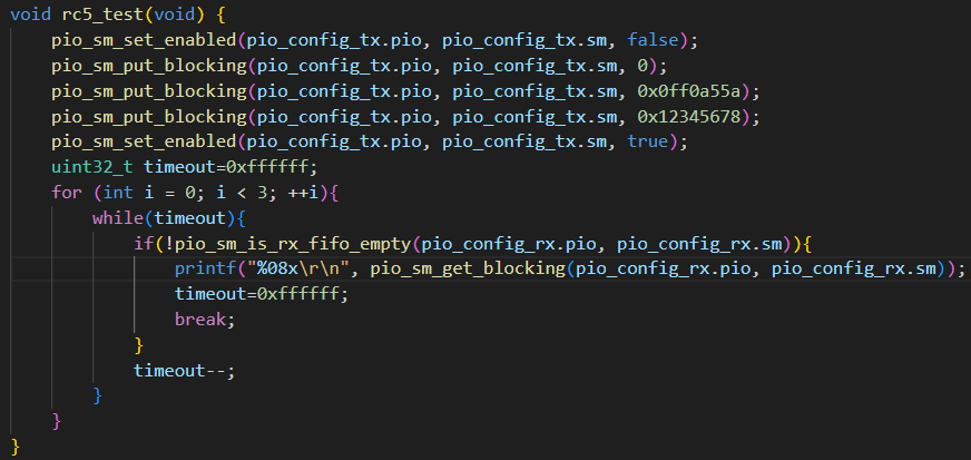
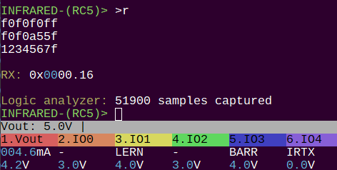
    pio_sm_put_blocking(pio_config_tx.pio, pio_config_tx.sm, 0x0);
    pio_sm_put_blocking(pio_config_tx.pio, pio_config_tx.sm, 0x0ff0a55f);
    pio_sm_put_blocking(pio_config_tx.pio, pio_config_tx.sm, 0x12345678);
Well look at that! The test data does not start with one, so it is invalid/ignored. Also note that RC5 is encoded LSB.
    pio_sm_put_blocking(pio_config_tx.pio, pio_config_tx.sm, 0xf0f0f0ff);
    pio_sm_put_blocking(pio_config_tx.pio, pio_config_tx.sm, 0xf0f0a55f);
    pio_sm_put_blocking(pio_config_tx.pio, pio_config_tx.sm, 0x1234567f);
After changing the LSB to 1 we have a “valid”-ish frame and everything works!
Next: cleanup, implementation, and testing with a real remote ![]()
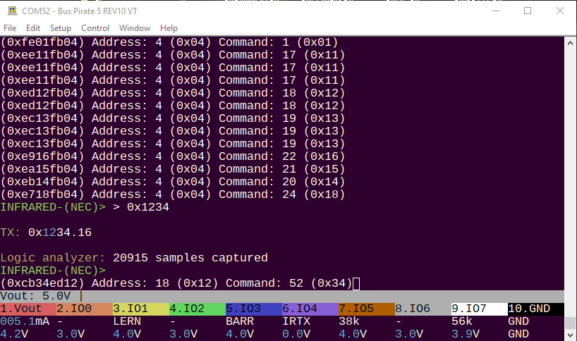
NEC protocol mode using universal remote and also transmitting back to itself.
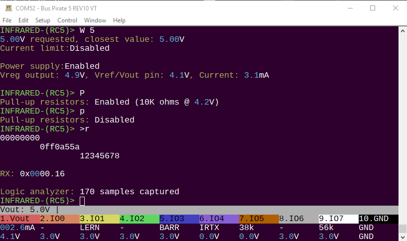
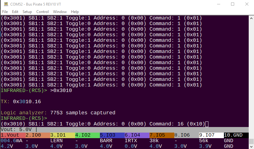
RC5 protocol using a universal remote and also reflecting IR back to itself. RC5 mode forces the stop bits (13, 14) to 1.
RC5 has a “toggle” bit.
- When holding a button down the toggle bit doesn’t change.
- When pressing multiple times it flips each time.
In the screenshot I’m pressing the “1” button (command 1). Each time I press the toggle bit flips 1/0. If I hold the button it repeats and the toggle bit stays the same. This remote will only repeat the numbers buttons 3 times and then stops. It will repeat the volume and channel buttons indefinitely.
.define public TICKS_PER_LOOP 16         ; the number of instructions in the loop (for timing) **2samples per bit = 16 not 8**
.define public NUM_BITS 14               ; the number of bits to receive per frame
.wrap_target
get_bit:
    in pins, 1 [6]       ; Read the bit, sleep 3/4 of a bit
    jmp y-- get_bit      ; collect all the bits
public entry_point:
    set y ((NUM_BITS*2)-2)  ; initialize the bit counter, with some delay to avoid triggering on previous bit
    in x, 1             ; Insert the invisible first half of the start bit
    wait 0 pin 0 [2]       ; Wait for the 1->0 transition - this is the middle of the start bit
.wrap
Every time I use a PICO SDK PIO example it is just too cute to function in the real world. Manchester decoding example works great as a demo, but in the real world waiting on pin state changes mean we get hopelessly out of sync and stuck in the state machine.
After a day of messing with it I decided to use the PIO to sample each half bit of the manchester encoded signal, then process the result in the firmware. This is more like a UART now. Advantages:
- No longer get stuck waiting for pin changes during invalid signals
- Inherent timeout and reset feature
- Firmware does the manchester decoding, so we can detect invalid/bad encoding and reject the data as invalid
I’m going to push this now. Would welcome feedback from anyone with the IR Toy plank.
Hi Ian,
Played around with this a (very) small amount. Something’s going awry with the prompt, after just entering and then exiting the mode:
HiZ> m 10
Use previous settings?
 RX sensor: 20-60kHz learner
 TX modulation: 38 kHz
 Protocol: NEC
y/n, x to exit (Y) > y
Mode: INFRARED

INFRARED-(NEC)> m 1
Mode: HiZ

HiZ-(NEC)>
Is having the suffix be persistent after exiting a mode expected?
I did not expect this, but am open to a reason for this be implemented this way that I’ve not thought of.
Trying to understand the mode more, and tried the INFRARED mode’s test command. I enabled power (W 5), but the test fails?
INFRARED-(NEC)> test
Test pull-ups
BIO1 / 20-60kHz learner: OK
BIO3 / 38kHz barrier: OK
BIO5 / 38kHz demodulator: OK
BIO7 / 56kHz modulator: OK
Test RX
BIO1 / 20-60kHz learner: FAIL
BIO3 / 38kHz barrier: FAIL
BIO5 / 38kHz demodulator: FAIL
BIO7 / 56kHz modulator: FAIL

4 FAILS :(

INFRARED-(NEC)>
Did I misunderstand some steps? On a hunch I put a nice white piece of paper in front of the emitters to reflect the IR, but it has the same result.
Thank you so much for the bug reports. I pushed a few updates:
- infrared mode cleanup removes the sub mode indicator
- infrared test plank function updated: now actually sends a frame with the current protocol and confirms that a frame is received
confirmed both items fixed.
I will get a new electronic energy meter installed next month. Those have an IR port that constantly sends out the meter count, meter id and similar stuff with 9600 baud UART.
If I understood the descriptions correctly this is not modulated, but raw 9600 baud UART. Is this something one of the receivers on the plank could get? The learner sounds like the one getting closest, but also having a lower limit that would be an issue.
When thinking about this I remember that better hand multimeters often also have an IR port that works like this. They use IR for isolation/safety reasons. They don’t need the modulation because the IR diodes sit in an encapsulated comms head that you plug into the multimeter, so no foreign light leaks in and could cause issues. This is similar with the energy meters where you usually attach a head with a magnet.
Maybe a raw phototransistor for these usecases could be added to a future version.
That is very interesting. If it is unmodulated 9600bps UART, yes probably an IR photo diode is needed. I’ll have a look at options.
