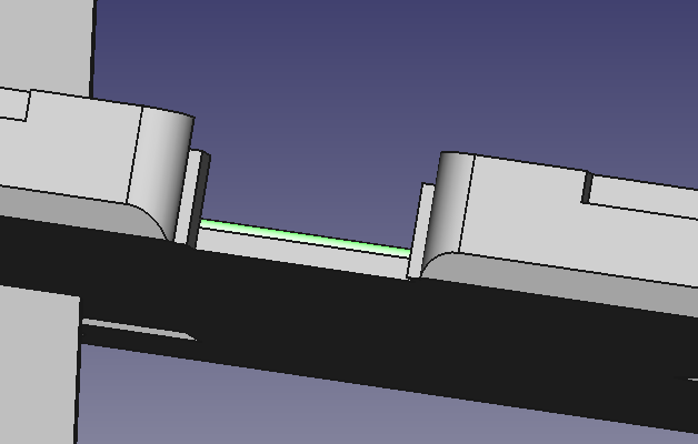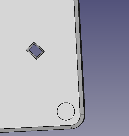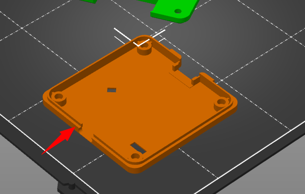
Almost there. Trying to get the AUX access as nice as possible. The rounded edge (green) is on the wrong side, it should be on the bottom. I presume we finish it tomorrow.

Almost there. Trying to get the AUX access as nice as possible. The rounded edge (green) is on the wrong side, it should be on the bottom. I presume we finish it tomorrow.
Did a test print. Couple observations. The silicone feet fit well with the added tolerance and the genuine 3M adhesive feet are really sticky.
However, with the feet installed it’s really hard to get into the packaging bag. Its also really though to get out. It possible the feet will be included to install yourself.
We’re going to see if a little more material can be removed around the AUX connector tomorrow, but it’s getting kind of thin (would be a 0.7mm retaining peg instead of 1.4mm.
Rounded this out a bit more, it wasn’t noticeable on the print.
With the side tabs even with the AUX connector.
With the side tabs pulled down a bit more exposing some room on the side to slip in tweezers or whatever and pop out the AUX cable properly.
Confession: I yank the AUX cable out by the wires, which you’re totally not supposed to do, and haven’t broken one yet. But, I know others are not so crass, and even recall one post about cutting material away for better access to AUX.

One late thing we’d like to change now that AUX is dealt with is the bootloader button hole shape. There was a suggestion for a flexible pad to assist pushing the button, or even just a smaller (~3-4mm) oval or round hole.
However, it took too long to get to this point. I’m terrified we’ll run out of cases just as Spring Festival hits and that would be a disaster (for the second year in a row). Fortunately the button hole is now an insert so we can mess with it later when we are not so tight for time.
BP-enclosure-rev3.zip (103.7 KB)
STEP file if anyone wants to check out the latest.
Does 3M offer their VHB family of industrial tape in pre-cut forms, such as 5mm disks?
As a younger engineer, our company built a huge system spanning several 19 inch racks of equipment, and used adhesive backed cable tie points for all of the wiring harnesses. Within a year, all of those had come loose and the cables were flopping in the breeze. My senior engineers drummed it into our heads after that, never use adhesive if you can avoid it.
That might be an extreme point of view. I realize threaded inserts and screws have been ruled out here. I’m wondering if the mold could have some kind of slot where rubber feet could be squeezed in, being held in place just by the shape of the foot and the slot. Just a wild thought.
I was thinking about this as well, a one-sided VHB tape. Evidently it’s really easy to customize adhesive stuff. @jin said all the factories where we bought silicone feet from do customization in pretty low quantities.
This feels like the project that will never end ![]() This weekend we rounded out the AUX access area. The latest SLA print was a tad tight, so we added 0.15mm more tolerance around the PCB.
This weekend we rounded out the AUX access area. The latest SLA print was a tad tight, so we added 0.15mm more tolerance around the PCB.
Rounded out AUX access.
Note: this is not injection molded, so not the final material. This is just how it looks with LEDs in SLA.
Hooray for the inserts.
I’m sure you’ve though of this, but just in case…
Have you verified fit using a board using the new 10p header soldered in? You know … just in case the tolerances from the new provider are off, or offset by “just enough” to cause fit’n’finish type issues.
Even in SLA, that’s looking good. It really can’t be overstated how important a good case is to the success of an electronic hacker product. (Case Study: Flipper Zero)
Glad to see it continuing to get some love.
Seems like we’re all done, tooling is being made. We’ll have samples in, optimistically, 30 days.
These should be the final design files. Includes STP, and STLs for each half. We were able to print it pretty easily with PLA on a Prusa Mini+.
case-v2-rev4.zip (475.5 KB)
Please share a photo if you make a print ![]()
@ian , I haven’t checked the file, but the result seems to be missing something.
Could be something on my end, but I’m out for tonight and will check back.
I do love the finish of the portion that printed!
Nice pictures, and great print quality, thank you for sharing!

Similar to enclosure v1, the USB connector should fit snugly in this cut out. It looks like a couple mm of the bottom half is missing.
Woah! That’s great. I’ve never used glow in the dark filament before.
Thanks. It came out VERY well for a draft print. The design seems solid and feels very refined so far. I am going to testfit connectors and get a better feel for it once its fully assembled tonight, right after I press in a few threaded heatpress inserts. I’m hoping I have the right size. Every time you think you have a little of everything, a different varient or size comes along. Being able to design what you want on the spot is nice, but takes more invengory than anyone talks about. ![]()
Looks like this one turned out great!