Is there a GPIO mode? Where I can set GPIO pins? LIke we have in the Flipper Zero, bitbang stuff.
1 Like
There is a binary bitbang mode. It works, but it is disabled in the latest firmware because I’ve been working on the logic analyzer today. It should be back when I update the SPI binary mode tomorrow:
How exactly do you want to bitbang? I’m working on this part of the code at the moment and I’d like to make it a little more friendly.
Ow, I see, no problem.
Ideally, I’d write to multiple GPIOs at the same time, the original scripting on BP v3 worked great for me. In my use case, I need to bitbang multiple pins at the same time, in a periodic manner.
The old BBIO mode is working, but it’s a bit limited because it imitates the old hardware and only gives access to 5 IO pins. I’ll make a super simple way to set direction and then write bytes to all 8 pins at once, I’m working on binary mode stuff now.
No worries, my BP v3 still works great ![]()
1 Like
How do you feel about using an escape character and XOR? It’s a little daunting in some scripting languages, but it makes control of the GPIO mode dead easy.
For example, 0x7E is the flag character indicating the beginning of a new API packet. With the AP=2 option, since 0x7E can only appear at the start of an API packet, if 0x7E is received at any time it can be assumed that a new packet has started regardless of length. Certain control characters must be escaped if they are to be interpreted as data and not as the control characters themselves. To escape an interfering data byte, insert 0x7D and follow it with the byte to be escaped XOR’d with 0x20. This allows the character to be passed as data. If the character is not followed by the escape sequence, the character is interpreted as a control character.
The following are all characters which need to be escaped:
0x7E Start frame delimiter.
0x7D Escape control character. Indicates that next byte is escaped.
0x11 0x13 These bytes are software flow control characters.
It seems to be used in zigbee stacks. I dealt with it my first microcontroller project - it didn’t go well so I understand it might not be for everyone.
It’s fine with me, to be honest i believe this is the way, but I do believe that for some it might be a pain in the a**
In python it’s dead simple to create simple function to do that. Don’t know others scripting langs though.
@Ian so, are there plans still to bring GPIO mode into menu? I personally find it very convenient, cause currently if I need to provide some odd signal level or toggle it (to reset DUT for example or indicate start of glitch sequence) I have to pick UART, which is a bit misleading and I loose two channels ![]()
I believe that was DIO in the old firmware, and sure, I’ll add it asap.
1 Like
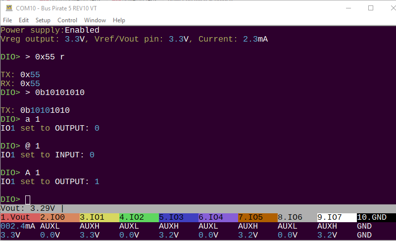
Just pushed DIO mode for terminal control of all 8 IOs. It should post in a few seconds.
All 8 IO pins can be controlled with the a/A/@ auxiliary pin command. It’s also possible to set all 8 IO pins at once using bus syntax writes (and reads).
2 Likes
Yep, I see it and it seems to work, but crashes if you type various chars like ? in this mode. Like
HiZ> m
Mode > 8
DIO> A 0
DIO> W 0
DIO> ?
Thank you. I pushed a fix.
1 Like
Confirmed. Works perfect now! Thanks!