Show UART transmission status via LEDs on the case:
I’m interfacing with retro calculators and the main method to upload data to them is via UART. But the calculators don’t echo the received data so when I’m using my Serial.app “Send String” feature I can’t monitor the progress whether it’s still happening or already done.
My current work-around is connecting a logic analyzer to bus pirate to monitor what’s happening on the data pins.
It would be nice to show the current transmission status with Bus Pirate’s LEDs somehow.
I was just thinking the same thing a couple days ago. Back in ye day as a young engineer, we would sometimes use the 74LS122 to stretch out serial data LED pulses to make them visible. I’m sure Ian will be taking a purely firmware approach
I tried to do this quickly, but it turned into a much larger project.
@henrygab - I tried to tackle this by passing a message from core 0 to core 1 that blinks the LEDs in the core 1 loop. The your inter core helpers are blocking and also wait for acknowledgement, which would slow down the UART bridge main loop if we send lots of activity indication packets.
Curious on your thoughts tackling something like this. Maybe you see a different way? It feels like the LEDs should be handled on core 1 because they already are, and so the UART bridge isn’t delayed with blocking writes of LED data out the PIO.
Maybe it is time to have a small DMA for LED frames instead of blocking until we get the last 8 words into the PIO buffer?
Now you see why a dedicated one-shot can be an attractive solution in some cases. I haven’t looked at the firmware design, but if you have a system timer it’s pretty easy to implement LED behavior like this with just a bunch of variables that hold a count value and a reload value and some very simple handler functions. Everything can be attached to a single timer peripheral.
I’ve used that approach for serial and even IR RX LEDs. Just shove a fixed value into a global each event. Another process watches and decrements it. If non zero turn on the LED.
Yeah, you miss some lie people, but it’s just a finger in the wind kind of thing.
There are too many LEDs to fit an update of the entire string in the PIO buffer, so we have to wait while it shifts out (or change to a DMA setup). So I tried to handle the update on the other core, but the way our inter core is currently setup is also blocking. It’s going to take some shuffling one way or another to get this going.
I pushed the first update towards this feature: the LEDs are now updated via DMA so we don’t block while the slow-ish protocol writes out 10 words (we have an 8 word FIFO, a total update is 18 words).
Next we’ll need some kind of mod to henry’s inter core stuff.
Ultimately I think the pixel driver will be updated so that we can layer effects over the currently active LED mode. So the LEDs on either side of the connector can flash red/TX green/RX or similar. Maybe with brightness relative to bus saturation?
There are two DMA buffers … one is active, while the other is used for preparing the “next” frame of pixel data.
The existing effects use a separate buffer to prepare their effects data.
Other callers also use a separate buffer to prepare their modifications.
I had prototyped the idea of “reserving” a set of pixels. e.g.:
uint32_t pixel_owner_tag[PIXEL_COUNT];
This provides an easy way to implement an API to:
Reserve some subset of pixels for a mode’s use (just set the owner tag to non-zero for those, failing if already an owner exists)
Once reserved, that owner prepares a buffer of the color values to be used (for simplicity, always full array of PIXEL_COUNT size).
Release ownership of pixels.
To update the displayed pixels, the owner calls a trigger function.
Existing effects will also call that trigger function.
If desired, it’s also easy to add an API to claim / update a single pixel. Note, however, there is no atomicity doing one pixel at a time.
tracking the owners this way is also helpful for debugging … as the owner tag is easily discovered. Can also print to console easily.
Psuedo-code for the trigger function does:
if triggered by effects:
for any non-owned pixel, copy the provided buffer’s colors to the new DMA buffer
if triggered by owner of some pixels:
for pixels matching the calling owner, copy the provided buffer’s colors to the new DMA buffer
Swap the buffer used for DMA (active becomes old, new buffer becomes active)
Copy the new buffer’s color data to the old buffer … the old buffer is now the inactive one and ready for partial updates.
I never submitted a PR, because there was no requirements for how we might want to use it. That said, the above is a strong design that can be adjusted for more complex effects in future.
I do NOT recommend the use of ICM for this purpose. ICM is a hack for early boot. As you noted, it’s blocking … because it’s a very, very limited communication technique. (and fragile! hic sunt dracones)
There’s a general question that’s not solved easily, at least not when you need to ensure Core1 never blocks (due to USB, etc.).
For this in particular (pixels), perhaps the DMA swap should simply be part of the Core1 loop (with USB, etc.)?
The triggering function would still do the same update of the buffer, but then simply set a flag indicating an update is needed. Since each pixel has an “owner” … the only conflict would be if a single owner attempts to update a pixel from both cores simultaneously.
Meanwhile, the main Core1 loop would check that flag, and perform the swap of active ← → inactive DMA buffer.
There’s still a slim chance that a set of pixel color updates would not be atomic, but it would only appear momentarily until the next Core1 loop, which should be effectively unnoticeable as the pixels would then be updated to the correct values entirely.
@Dreg had a clever solution that bypasses all the two core issues. Just use the GPIO interrupts on the related pins to trigger the activity indication. Then the bridge loop doesn’t need any modification.
If any effect is enabled, wouldn’t that overwrite whatever happens there?
My idea of having an “owner” for each pixel was to allow for a coherent “merge” of the standard effects functions’ output + a buffer that the “owners” provide for their pixels.
Using @Dreg’s clever solution works with this … its ISR simply writes the value to the “tag owner” color buffer at the proper index.
This way, while the UART is running, other pixels can be used for additional purposes without conflicts. And it’s very, very low overhead.
Yes there would have to be a hook to assign an owner or method for certain LEDs. The first pass advances the next frame of any active animation, then a second pass overlays any hooks onto various leds.
I explained poorly, but the main point was the benefit of the LEDs being managed completely from core 1 in rgb.c without interaction from the bridge function.
What I have in mind is a hook system for registering the second pass functions (much like fala). Before starting the UART bridge the command registers an interrupt handler and a second pass handler. On pin interrupt reset a counter. In second pass check counter and optionally make changes to relevant pixels.
Are you suggseting the second pass handler is effectively registering a callback function?
If so, I do not recommend this for a few reasons. I’ll try to explain here rapidly, can fill in based on your questions:
harder to debug when something goes wrong
swapping between two DMA buffers can easily occur
timing of the callbacks is not related to the updates
In contrast, if the callers modify an inactive buffer (via an API), and then (via an API) indicate an update is ready, this minimizes the locks, while allowing updates to occur immediately (if called from the core doing the DMA buffer swap, e.g., Core0), and in one loop iteration when caused by the other core (e.g., Core1).
No function pointers, easy to follow and debug code, and no dangling pointer surprises … because the buffers are statically allocated.
After reserving the pixel, the interrupt routine would just call the update routine (which all it does is set a memory location to the value of the parameter, and set a flag or swapping DMA buffer, so it’s OK). So, your goals are met…?
This is just a test to see how it looks in practice.
static inline void update_pixels(void) {

    for (int i = 0; i < COUNT_OF_PIXELS; i++) {

        //check if an overlay function is assigned to this pixel
        if (pixel_overlay_function[i]){
            //call the overlay function
            pixels[i] = pixel_overlay_function[i](i, pixels[i]);
        }

        // little-endian, so 0x00GGRRBB  is stored as 0xBB 0xRR 0xGG 0x00
        // Shifting it left by 8 bits will give bytes 0x00 0xBB 0xRR 0xGG
        // which allows the PIO to unshift the bytes in the correct order
        CPIXEL_COLOR c = pixels[i];
        c.r = c.r / system_config.led_brightness_divisor;
        c.g = c.g / system_config.led_brightness_divisor;
        c.b = c.b / system_config.led_brightness_divisor;
        rgb_dma.buffer[i] = (c.g << 24) | (c.r << 16) | (c.b << 8);
    }
    if(!dma_channel_is_busy(rgb_dma.chan)){
        //dma_channel_configure(dma_chan, &c, &pio_config.pio->txf[pio_config.sm], dma_buffer, COUNT_OF_PIXELS, true);
        dma_channel_set_read_addr(rgb_dma.chan, rgb_dma.buffer, true);
    }
}
I added a check in the main pixel update loop to process overlays before converting to the final transmission format and activating DMA.
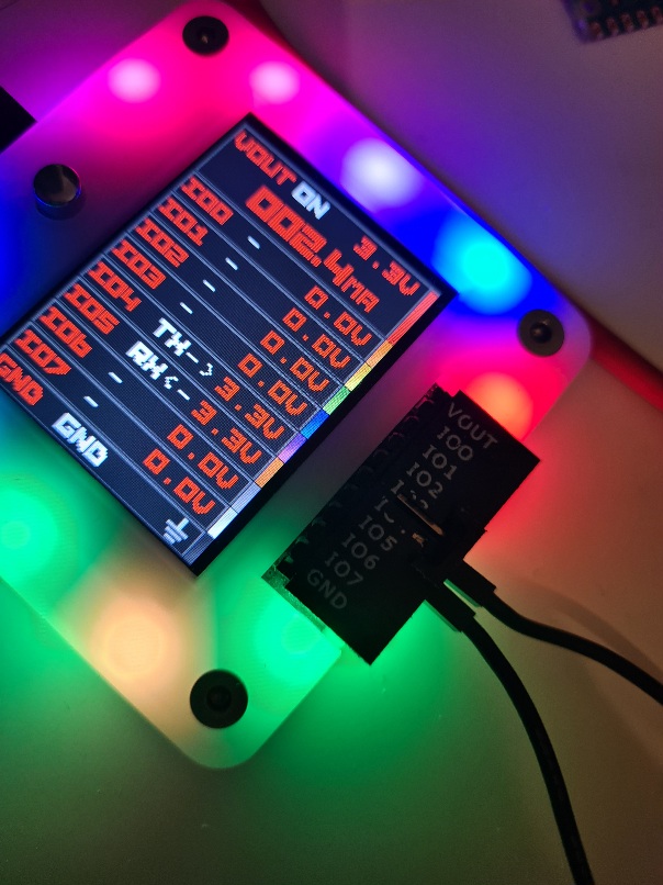
Visually I think it looks pretty good. Here the pixel under the connector and the pixel next to it are assigned an override. Top/TX is red, bottom/RX is green.
Next I’ll test the gpio interrupt driven blinking. Pretty sure the delay timer should be serviced in update_pixels to avoid race conditions (as opposed to an interrupt function).
I’m just playing at the moment. I see a lot of possibilities and opportunities to make it pretty flexible.
Could you help me walk through a few things (e.g., confirming or correcting my understandings)?
The overlay callback function is called at a time controlled by one of the cores. Let’s just presume it’s Core1 (not critical).
Are overlay functions expected to get data dynamically, or is there a presumption that the data buffer to be overlaid already exists?
If data buffer to be overlaid already exists … what is preventing updates to that data during the overlay callback?
If data is generated dynamically … and data source has no control over callback timing, …
It appears that each provider of overlay data would thus need to handle their own locking / sychronization. Is that accurate?
If this is running on Core1, wouldn’t that break the “no blocking APIs” requirement that Core1 has (to ensure USB response times, LCD updates, voltage adjustments, …)?
I can definitely see this working where the callbacks can only interact with buffers provided to them. Examples where a callback works well include:
overlaying a fixed color
applying a brightness limiter
limiting current (similar to brightness limiter, different purpose)
animations that blend two or more pixel color buffers
animations that define a next frame based solely on the current color buffers
Put another way:
Does your solution ensure that the DMA’d buffer always either:
Represents a consistent set of color data, OR
Ensures the inconsistent color data exists for a maximum of one Core1 loop + 1 DMA cycle?
Similarly, where is the work done to ensure the above data consistency?
If the intent is that the callback overlay function is going to be dynamically generated data (e.g., from a mode giving update), that would mean the overlay functions have
At the moment I am playing with the aesthetics of the blink (150ms red, 100ms white is kind of nice) and learning what the project requirements might be.
// overlay function forces a pixel to red
void overlay_function(int led_num, CPIXEL_COLOR *pixel) {
    if(pixel_overlay_active[led_num] == true){
        *pixel = pixel_overlay_color[led_num];
    }else{
        *pixel = PIXEL_COLOR_WHITE;
    }
}
The overlay is written directly into the pixel buffer before it is processed and DMAed, so there shouldn’t be an opportunity to change pixels during DMA.
All of the interrupts just manipulate control variables, not the application of the overlay itself. None of this is set in stone, I need to poke around to see what might be useful and a rational way to implement it.
For example, now I realize that maybe instead of using GPIO interrupts (which does not correspond to data) it is better to attach the uart rx/tx interrupts so it only blinks on valid data. Same with SPI, etc. Now I need to figure out how to pass that in as a config struct and handle all the interrupts in a clean way.
This is very very hacked together, but you can see the effect in UART bridge mode:
m uart
W 3.3
bridge
<type some characters>
The TX side LED with be white and blink red when you type into bridge mode. It is on 150ms, off 100ms, so it doesn’t stick on red during continuous data transfer.