BTW, There is a discussion on the Jumperless forum on integrating the BusPirate and the Jumperless
I believe @BusPirateV5 was also talking about this. It sounds cool. Let me know if there is anything I can help with.
Oh hey @ian! Love your work, I’ve been a total fanboy since the BP 3 days.
Anyway, I just sent these off for a test batch.
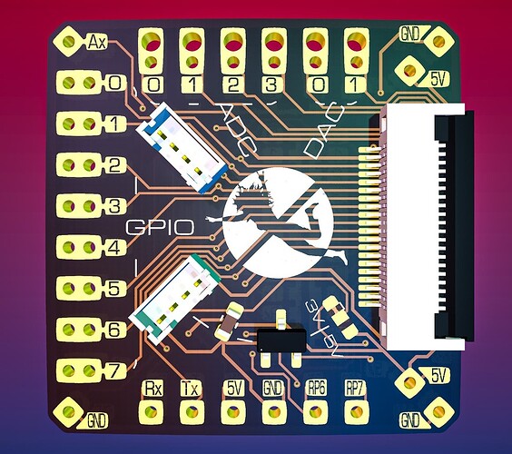
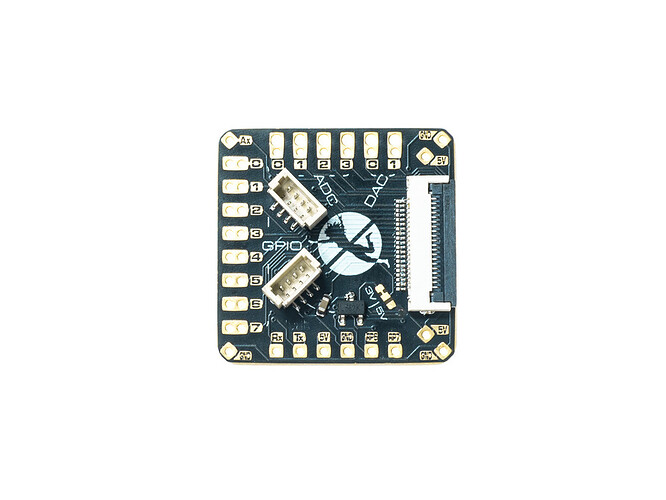
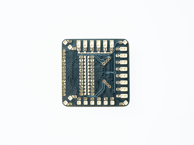
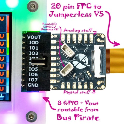
It’s a little adapter board that (among other things) plugs into a Bus Pirate header so the GPIO lines/VOUT are routable anywhere on the Jumperless. I’m like 90% sure I’ll be including these in the box.
So, I’ve been meaning to ask if there’s any way to do a sort of side-channel data-in thing, either though the GPIO or a separate header on the board where I cold have the Jumperless send where the lines are routed (or whatever data), and then have that show up on the BP’s screen.
Not super important, but it would be cool to just generally have them coordinate.
It could be doable. The only issue I see is that the pins used for protocols often change and there’s currently no consistent set of free pins for the jumperless IO.
This would just be input?
Good point, I’ll ruminate on that and see if some clever way to handle it pops up.
All 8 pins are also hardwired to the RP2350B, and Jumperless already does a bunch of scanning stuff like that, so maybe the Bus Pirate could just use whatever pins aren’t being used for protocols and the Jumperless could check them all for valid data?
Or use the Vout pin (which can connect to an ADC) and do analog signaling somehow? Then if you wanted to use it as a power supply the Jumperless could just use one of its own.
Another silly thing is that in broad strokes, they both kinda have the same hardware available (except that yours is much better protected/well designed for this), you could almost run BP firmware inside Jumperless’s with some translation layer. It would be a bit janky/slower/less accurate, but it could be cool to keep a familiar UI.
The hope would be to eventually make it bidirectional. Even without doing any of this, a Bus Pirate could control a Jumperless by just sending it a list of connections over the UART lines as text.
Like (the leading f is to tell it to accept a new netlist)
f adc0-1, 2-34, dac0-3, gpio6-4,
idk, I’m just kinda brainstorming here. It’s really non-critical and would be totally fine without any of this. But if we ever end up with any free time (unlikely), it would be a fun thing to work on.
Okay reading this topic about planks gave me a really stupid idea I know I’ll never get around to.
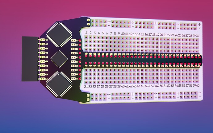
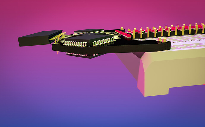
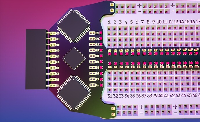
I threw it together in Kicad (just putting parts on a PCB, there’s no schematic) just in case someone wants to run with this idea and make it their own, I’d be happy to help.
Those 2 chips (plus 1 on the back) are CH446X 5x24 analog crosspoint switches, and the small one in the middle is an RP2040 to control them.
The idea is that it’s basically 1/3rd of a Jumperless (and hopefully less than 1/5th the price if it ever gets made), and lets you route any of the Bus Pirate’s pins anywhere a breadboard, and those addressable LEDs will light up with a unique color to show where each signal is going.
You could also do some Jumperless-style routing/sensing/measurement, just with more limitations for how much can be connected at one time.
So there’s my hare-brained idea and I hereby release it to whoever wants to actually make it.
Plankerless.zip (102.0 KB)
This just might happen soon. Video will be released if it does.
This could be very handy.
The latest Jumperless is amazing! I got caught up this weekend, the demo video is so cool. Immediately pulled the schematic to see how it works, the LED page is impressive.
There’s a 2021-ish vintage discussion on Jumperless github (first page google result for CH446X) that was a nice primer.
This fits last week’s project. We worked up a “blank plank” for prototyping. I also looked at bread board-y type things, but from a completely different perspective (no automated signal routing or anything like that).
Something like this would be an opportunity to figure out the Bus Pirate to Jumperless communication channel.
Would splitting the center arm into two arms that go on the outside rows make sense? So that DIP (adapter) chips don’t straddle the PCB and obstruct the view of the LEDs?
The breadboard “arm” has 30 pins, so 2 CH446Xs are used per side? I assume the 8 Y ports are the Bus Pirate IO pins.
Are power and ground also routed through the CD446X? Just trying to wrap my head around how that would work without an additional 4 chips.
I’m really excited about this! I hope it does happen!
Hey thanks! It means a lot from the guy whose project kinda got me into electronics.
Haha yeah that’s a much better idea. And then you could label the rows so you can be sure they match the software.
Just throwing it out in case someone has a use for these in a plank like that:
If you want to make something with these at volume, I can just tell the manufacturer it’s cool if you use my tooling and you can order directly from them (they’ll be like $0.15 per clip). These were just a thing I needed to make Jumperless work, I couldn’t care less about making money off them.
Yeah they can be. How I do it on the Jumperless is to give the breadboard rails a direct connection, so you can push as much current as the power supply can offer through them, and also let them be routable. The resistance of the 2 crosspoint connections comes out to ~80ohms, less if you “stack” and run them in parallel. The idea of a “current limit” doesn’t really apply because it’s handled by that resistance, they can handle [12V / 80ohms =] 150mA just fine.
On this plank thing, I have no idea, the schematic is a vague blur in my head at this point. But it probably would be useful to make them routable too.
Okay now the interesting part:
It’s gonna take quite a bit of staring at it to find an arrangement that works. Which in this case means “lets you connect all 8/9 BP pins to any set of rows at the same time” and bonus points if you can do it with 3 crosspoints (either 8x16 or 5x24). I know it could be done in 4.
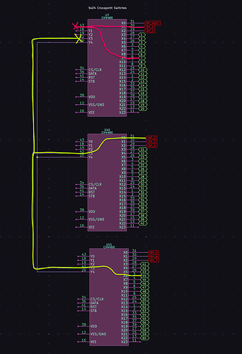
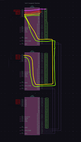
I don’t think any of these are the winner, but here are some arrangements I was just screwing around with:
This is kinda close-ish, idk about having bussed connections between all 3 though. The issue is that you can run out of free paths pretty easily, like even having
Bus Pirate   0 1 2 3 4 5 6 7
             | | | | | | | |
Breadboard   1 2 3 4 5 6 7 8
wouldn’t work. But it does show how you can do a “bounce” with a crosspoint switch and route a signal back to the same side, as long as there’s an unused input on the other side.
Also not a winner, using 5x24 crosspoints kinda limits you to 5 things connected on that section of breadboard.
You could also do it it in a super straightforward way with 4 8x16s, but routing Vout would also mean it’s connected to one of the bus pirate inputs.
So yeah, none of these are the right way to do it, but I’m just kinda showing my thought process for how I come up with arrangements of crossbar switches to make something arbitrarily routable. My process is basically guessing and then trying to find a situation where it doesn’t work. It’s a fun puzzle, and I’m 100% confident there is a good solution.
Here are the Kicad files (copied from a shelved project so there’s some irrelevant crap in it) if you want to rearrange stuff and see if you can crack it.
PlankSense.zip (243.0 KB)
Bonus really stupid idea for BP7: what if you hooked up two of the screws to spare RP2350B pins and used them as the communication link between it and the Jumperless?
I thought about something like this for automatically identifying planks. So you plug in the IR-plank, then the software automatically suggests you activate the IR mode or something like this. This side channel would of course be usable for similar things too.
The difficult part is how to create this side channel mechanically. I thought about extnding the 10 pin connector to 12 pins. but this has to be done symmetrically to be also compatible with existing planks and plugs. I didn’t really like this idea so I didn’t write anything about it.
I think some additional small connector might be the way to go. But getting it into the case isn’t going to be easy. Also needs space on the pcb and must be mechanically robust. So I’m not sure if all this effort is worth it.
I’m not really convinced by the screw-idea, because you want a robust electrical connection and I don’t think the screws will provide that. Their surface and internal connection to the pcb just isn’t made for this. Relying on the user regularly cleaning their screws isn’t what I call user friendly or reliable.
So, how big would such a side channel have to be?
The traditional way would be to use I2C. This is what for example oscilloscope vendor probes do or what is used in SFP network optics modules. You’d need 3 extra connections for this: Aux 3V3, SCL, SDA. The Aux 3V3 is necessary to power the detection circuitry before Vout is activated - because the plank should be able to tell what it’s voltage limits are. GND could use the regular main GND. On the plank itself you’d just need an I2C eeprom in the most basic version, once you got the connector it is essentially free.
An alternative would be to use Onewire. In the parasitic power option you would just need one extra pin, GND would use the 10p connector. But I’m not sure if parasitic power works with all kinds of devices, like microcontrollers. So better use Aux 3V3 and data. Downside is that the protocol is designed for devices only to be dedicated ASICs, not microcontrollers. I remember trying to implement it on an Attiny many years ago and it failed the timing requirements by far. Also it was littered with patents. But they could be expired by now. But one could use a modified onewire protocol with more relaxed timing to allow microcontroller-based devices. This would bring the per-plank costs down to like 10-15 cents for one of the cheap micros from WCH, Puya and the likes. But still more complicated than just using an I2C eeprom.
Regarding the connector: one idea would be to extend the Aux connector or replace it with a different connector style. I think this is more flexible regarding compatibility with existing planks and stuff users have built for themselves than the main 10p connector. But is it mechanically possible & stable for a plank to hook up both connectors? Also it could mean the new case would have to be adapted for creating an opening for this larger connector.
Thank you for the diagrams. The datasheet mentioned using a Y to cross back to an X, but it seems like you’d run out of resources quickly. I’m starting to get what you mean.
I thought about using the D part with 5x24 - four of them, 2 serving the 10 BPIO signals on each side. Sure it doesn’t cover a full small bread board, but it seems more straight forward for a first prototype. However there is then the issues of connecting things together on the bread board, not just to BPIO pins. More thinking to do.
That does seem like the most straightforward, kinda elegant way to do it. Especially if it’s more of a single purpose thing just for hooking up a Bus Pirate to a breadboard and users are okay with those limitations.
It’s really easy to fall into the mentality that there should be nearly no (easily found) limits for routing and end up with a 12 chip Jumperless (even then I would have put one more if CH444Q if it would physically fit, ha)
But if you, @ian, are into the idea of a routable breadboard plank like this, I’ll give it some more thought too because it sounds like fun. It basically comes down to how much it’s allowed to cost vs how arbitrarily routable it should be.
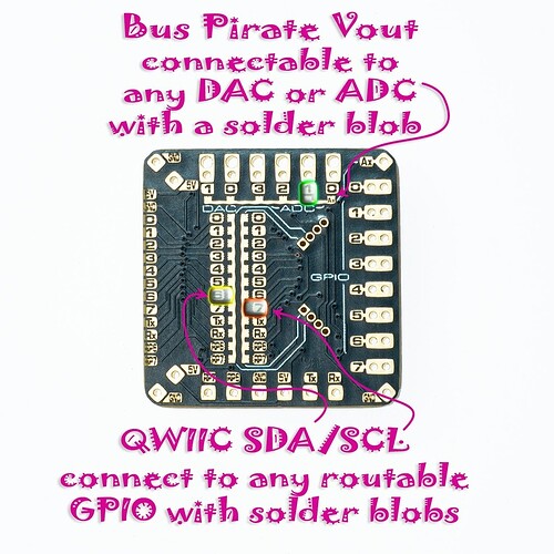
On the far end of that spectrum, the Bus Pirate (among other things) adapter boards for the Jumperless V5 just came in.
Until the V5 r4 prototypes get in, I have nothing to connect to the other side of that 20 pin FPC cable. So I made these totally normal adult human explainer guides:
These are cheap as hell and I ordered a bunch of them (it’s the thing they connect to that’s expensive), so if anyone wants some of these to play around with, let me know and I’ll send some out.
I should also mention these will be included in the box with every Jumperless V5, so if that’s what you want to use this for, just wait.
I am definitely interested in some of these!
Interested
DM me when you get a chance.
I am still very interested in this project. I asked the our CAD guy to look into routing feasibility a bit, but this is precisely were we got hung up. I had a hard time embracing the limitations, and stop thinking that everything needs to be connected to everything else…
Your previous explainer shifted my thinking a lot. Then I got a bit overwhelmed and realized it needed more thought ![]()
The 8x16 makes a ton more sense in the context of a bus, instead of using it as an actual matrix that connects everything to everything.
Can we state then that the “goal” is to support 8 routes, that can be connected to multiple pins? One breadboard pin to one or more breadboard pins, or one bus pirate pin to one or more breadboard pins? If this is the design goal, it seems like a much more straight forward project.
Also we’ll use some pins just to drive the plank. I suppose the best bet is what you showed above, a 2040 on the plank that does the 3/4 wire interface to the matrix chips and drives the LEDs. In that case we could get away with a I2C interface (2 pin) or even a bidirectional half duplex UART (1 pin).
The “totally normal adult human explainer guides” made me laugh out loud ![]() The board looks great, very daring to go FPC
The board looks great, very daring to go FPC ![]()
