I wrote a script to extract all the help from every command so I can review it in one place easily.
Help extraction
Bus Pirate Command Help Reference
Auto-generated by helpcollect.py. Do not edit manually.
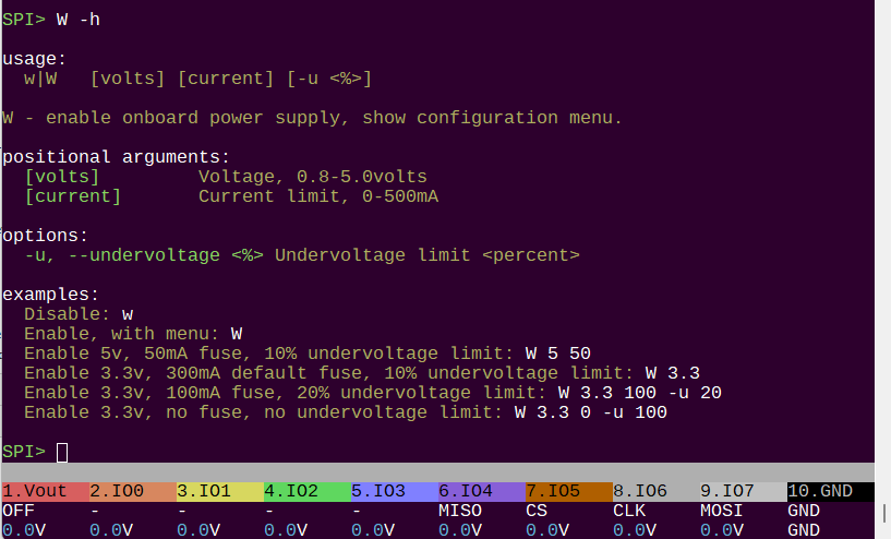
W
W -h
usage:
w|W <v> <i> [-u <%>]
Disable: w
Enable, with menu: W
Enable 5v, 50mA fuse, 10% default undervoltage limit: W 5 50
Enable 3.3v, 300mA default fuse, 10% default undervoltage limit: W 3.3
Enable 3.3v, 100mA fuse, 20% undervoltage limit: W 3.3 100 -u 20
Enable 3.3v, no fuse, no undervoltage limit: W 3.3 0 -u 100
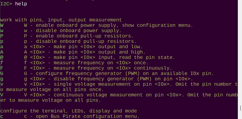
W - enable onboard power supply, show configuration menu.
-u, --undervoltage <%> Undervoltage limit <percent>
HiZ>
w
w -h

usage:
w|W	<v> <i> [-u <%>]
Disable: w
Enable, with menu: W
Enable 5v, 50mA fuse, 10% default undervoltage limit: W 5 50
Enable 3.3v, 300mA default fuse, 10% default undervoltage limit: W 3.3
Enable 3.3v, 100mA fuse, 20% undervoltage limit: W 3.3 100 -u 20
Enable 3.3v, no fuse, no undervoltage limit: W 3.3 0 -u 100

w - disable onboard power supply.

HiZ>
P
P -h

P - enable onboard pull-up resistors.
HiZ>
p
p -h

p - disable onboard pull-up resistors.
HiZ>
a
a -h

usage:
a/A/@ <io> [-h(elp)]
Pin 0 ouput, low: a 0
Pin 2 output, high: A 2
Pin 5 input, read value: @ 5

a <IOx> - make pin <IOx> output and low.

HiZ>
A
A -h

usage:
a/A/@ <io> [-h(elp)]
Pin 0 ouput, low: a 0
Pin 2 output, high: A 2
Pin 5 input, read value: @ 5

A <IOx> - make pin <IOx> output and high.

HiZ>
@
@ -h

usage:
a/A/@ <io> [-h(elp)]
Pin 0 ouput, low: a 0
Pin 2 output, high: A 2
Pin 5 input, read value: @ 5

@ <IOx> - make pin <IOx> input, read the pin state.

HiZ>
f
f -h

usage:
f [pin]
Measure frequency once: f
Measure frequency on pin 2: f 2

f <IOx> - measure frequency on <IOx> once.

HiZ>
F
F -h

usage:
F [pin]
Continuous frequency measurement: F
Continuous frequency on pin 2: F 2

F <IOx> - measure frequency on <IOx> continuously.

HiZ>
G
G -h

G - configure frequency generator (PWM) on an available IOx pin.
HiZ>
g
g -h

g <IOx> - disable frequency generator (PWM) on pin <IOx>.
HiZ>
v
v -h

usage:
v/V [io]
Measure pin 0 voltage: v 0
Continuous measurement pin 0: V 0
Measure voltage on all pins: v
Continuous measurement on all pins: V

v <IOx> - single voltage measurement on pin <IOx>. Omit the pin number to measure voltage on all pins once.

HiZ>
V
V -h

usage:
v/V [io]
Measure pin 0 voltage: v 0
Continuous measurement pin 0: V 0
Measure voltage on all pins: v
Continuous measurement on all pins: V

V <IOx> - continuous voltage measurement on pin <IOx>. Omit the pin number to measure voltage on all pins.

HiZ>
c
c -h

c - open Bus Pirate configuration menu.
HiZ>
d
d -h

d - change display mode, show selection menu.
HiZ>
o
o -h

o - configure number output display format.
HiZ>
l
l -h

usage:
L
Set bit order to MSB-first: L

l - set Most Significant Bit output order.

HiZ>
L
L -h

usage:
l
Set bit order to LSB-first: l

L - set Least Significant Bit ouput order.

HiZ>
cls
cls -h

usage:
cls
Clear and refresh the terminal screen: cls
Note: will attempt to detect and initialize VT100 ANSI terminal

Clear and reset the terminal

HiZ>
i
i -h

usage:
i
Display system information: i

i - show Bus Pirate info and status screen.

HiZ>
reboot
reboot -h

usage:
reboot
Reboot the Bus Pirate: reboot

reboot - reboot and restart the Bus Pirate.

HiZ>
$
$ -h

usage:
$
Jump to bootloader for firmware updates: $

$ - reset and enter bootloader mode for updates.

HiZ>
~
~ -h

usage:
~	[-h(elp)]
Run self-test: ~
Warning: Disconnect any devices before running self-test
Warning: Self-test is only available in HiZ mode

run a complete system self-test

HiZ>
bug
bug -h

usage:
replicate hardware bugs
Test errata E9: bug e9

HiZ>
ovrclk
ovrclk -h

!!ovrclk is in demonstration mode!!
To enable overclocking, recompile with BP_OVERCLOCK_ENABLED defined

usage:
ovrclk 	[-m <MHz> | -k <kHz>] [-v <core mV>]
Overclock: ovrclk -m 135
Change core voltage: ovrclk -v 1150 (850-1300mV valid)
-m, --mhz <MHz>
-k, --khz <kHz>
-v, --volt <mV>

HiZ>
smps
smps -h

usage:
smps	<v> [-s]
Set SMPS to <v> volts:  smps 12.3
Show SMPS ADC setpoints (diagnostic): smps -s

Switch mode power supply (plank required)
-s, --setpoints Show calculated ADC setpoints

HiZ>
jep106
jep106 -h

usage:
jep106 <bank number> <vendor id>
Lookup JEP106 ID (Micron): jep106 0x00 0x2c
Lookup JEP106 ID (Sinker): jep106 0x0a 0xab

lookup vendor name from 2 byte JEDEC JEP106 ID code

HiZ>
ls
ls -h

usage:
ls <dir>
Show current directory contents: ls
Show directory contents: ls /dir

list files and directories on local storage

HiZ>
cd
cd -h

usage:
cd <dir>
Change directory: cd dir

change to a directory on local storage

HiZ>
mkdir
mkdir -h

usage:
mkdir <dir>
Create directory: mkdir dir

create directory on internal storage

HiZ>
rm
rm -h

usage:
rm [<file>|<dir>]
Delete file: rm example.txt
Delete directory: rm dir

delete file or directory on local storage

HiZ>
cat
cat -h

usage:
cat <file>
Print file contents: cat example.txt

print file contents as text

HiZ>
hex
hex -h

usage:
hex <file> [-s <start address>] [-b <bytes>] [-p (disable pager)] [-a (disable address column)]
Print file contents in HEX: hex example.bin
Print 32 bytes starting at address 0x50: hex example.bin -s 0x50 -b 32
Disable address and ASCII columns: hex example.bin -q
press 'x' to quit pager

Print file contents in HEX format
-s, --start <addr> Dump: start address
-b, --bytes <count> Dump: number of bytes
-q, --quiet     Dump: quiet mode, disable address and ASCII columns
-c, --nopager   Dump: disable pager

HiZ>
format
format -h

usage:
format
Format storage: format

erase and format internal storage in FAT16 format

HiZ>
label
label -h

usage:
label [get|set] <name>
Get flash storage label name: label get
Set flash storage label name: label set <name>

get or set the disk label
get             returns the current label of the disk
set             sets the current label of the disk

HiZ>
image
image -h

usage:
Read BMP info and display image file on LCD
Usage: image <file> [-d] [-h]
Read info: image example.bmp
Draw on display: image example.bmp -d
Read formats: BITMAPINFOHEADER V1 (40Bytes), V2 (52B), V3 (54B)
Draw formats: 16-bit (565) and 24-bit bitmaps, 240x320 pixels

Write a bitmap image on the LCD
-d, --draw      Draw the image on the LCD

HiZ>
dump
dump -h

usage:
dump <bytes> <file>
First, manually setup a read from the device
Then, run this command to read X bytes to a file
Read X bytes to a file: dump 256 example.bin

dump <file> <device> - dump contents of flash <device> to <file>. Warning: currently a prototype that only works with 25LC020 in SPI mode.

HiZ>
otpdump
otpdump -h

Invalid command: otpdump. Type ? for help.
HiZ>
script
script -h

usage:
script <file> [-p(ause for <enter>)] [-d (hiDe comments)] [-a(bort on error)] [-h(elp)]
Run script: script example.scr

Script files:
Script files are stored in text files with the .scr extension
Lines starting with '#' are comments
Other lines are inserted into the command prompt
Exit with 'x' during execution
Example:
# This is my example script file
# The 'pause' command waits for any key press
pause
# Did it pause?

Run script files, automation
-p, --pause     Pause after each line for manual <enter> key
-d, --hide      Hide comment lines starting with #
-a, --abort     Exit script on error

HiZ>
button
button -h

usage:
button [short|long] [-f <file>] [-d (hiDe comments)] [-e(xit on error)] [-h(elp)]
Assign script file to short button press: button short -f example.scr
Assign script file to long button press: button long -f example.scr
Exit script on error option: button short example.scr -e
Default script files are 'button.scr' and 'buttlong.scr' in the root directory

Assign script file to button press
short           Assign script file to short button press
long            Assign script file to long button press
-f, --file <file> Script file to assign to button press
-d, --hide      Hide comments
-e, --exit      Exit script on error

HiZ>
macro
macro -h

usage:
macro <#>
	[-f <file>] [-a] [-l] [-h(elp)]
Load macros: macro -f <file>
List macros: macro -l
Run macro 1: macro 1
Macro system help: macro -h

Macro files:
 Macros are stored in text files
 Lines starting with '#' are comments
 Lines starting with '#!' are macro usage instructions
 Every macro line includes an id (>0), a separator ':', and commands
Example:
 # This is my example macro file
 #! Read 5 bytes from an I2C EEPROM
 1:[0xa0 0][0xa1 r:5]

Run macros, load a macro file
-a, --all       List all macro files on storage
-f, --file <file> Macro file to load
-l, --list      List all macros in active macro file

HiZ>
pause
pause -h

usage:
pause and wait for any key: pause
pause and wait for button press: pause -b
pause and wait for button or any key: pause -b -k
'x' key to exit (e.g. script mode): pause -x

Pause for user input, optional exit
-k, --key       Press any key to continue (default)
-b, --button    Press the Bus Pirate button to continue
-x, --exit      'x' key to exit (e.g. script mode)

HiZ>
logic
logic -h

usage:
logic analyzer usage
logic	[start|stop|hide|show|nav]
	[-i] [-g] [-o oversample] [-f frequency] [-d debug]
start logic analyzer: logic start
stop logic analyzer: logic stop
hide logic analyzer: logic hide
show logic analyzer: logic show
navigate logic analyzer: logic nav
configure logic analyzer: logic -i -o 8 -f 1000000 -d 0
set base pin (0=bufdir, 8=bufio): -b: logic -b 8

logic analyzer control
start           start logic analyzer
stop            stop logic analyzer
hide            hide logic graph
show            show logic graph
nav             navigate logic graph with arrow keys, x to exit
-i, --info      show configuration info
-o, --oversample <rate> set oversample rate, multiplies the sample frequency
-f, --frequency <freq> set sample frequency in Hz
-0, --lowchar <char> set character used for low in graph (ex:_)
-1, --highchar <char> set character used for high in graph (ex:*)
-d, --debug <level> set debug level: 0-2
-b, --base <pin> show configuration info

HiZ>
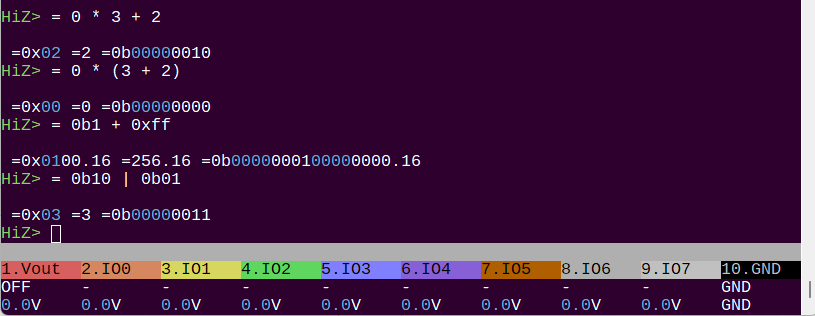
=
= -h

usage:
= <expression>
Convert: = 0x12
Math: = 0xFF & (1<<4)
Ops: + - * / & | ^ ~ << >>

= <value> - convert <value> to BIN/DEC/HEX/ASCII.

HiZ>
|
| -h

usage:
| <value>
Inverse bits: | 0x12345678

| <value> - inverse the bits in <value>.

HiZ>
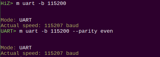
m
m -h

m - change protocol mode. m <mode number> to skip the menu.
HiZ>
binmode
binmode -h

usage:
binmode
Configure the active binary mode: binmode

Select binary mode
Active binmode: BPIO2 flatbuffer interface

HiZ>
scan
scan -h

usage:
scan	[-h(elp)]
Scan 1-Wire address space: scan

scan for 1-Wire devices

1WIRE>
eeprom
eeprom -h
usage:
eeprom [dump|erase|write|read|verify|test|list|protect]
[-d <device>] [-f <file>] [-v(verify)] [-s <start address>] [-b <bytes>] [-h(elp)]
List available EEPROM devices: eeprom list
Display contents (x to exit): eeprom dump -d ds2431
Display 16 bytes starting at address 0x10: eeprom dump -d ds2431 -s 0x10 -b 16
Erase, verify: eeprom erase -d ds2431 -v
Write from file, verify: eeprom write -d ds2431 -f example.bin -v
Read to file, verify: eeprom read -d ds2431 -f example.bin -v
Verify against file: eeprom verify -d ds2431 -f example.bin
Test chip (full erase/write/verify): eeprom test -d ds2431
Show write protect control block: eeprom protect -d ds2431
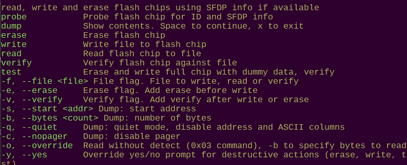
read, write and erase 243X series 1-Wire EEPROM chips
dump Show contents. Space to continue, x to exit
erase Erase chip
write Write file to chip
read Read chip to file
verify Verify chip against file
test Erase and write chip with dummy data, verify
list List supported EEPROM devices
protect Show chip write protect status
-d, --device <device> Specify the EEPROM device
-f, --file <file> File to write, read or verify
-v, --verify Verify after write, read or erase
-s, --start <addr> Dump: start address
-b, --bytes <count> Dump: number of bytes
-q, --quiet Dump: quiet mode, disable address and ASCII columns
-c, --nopager Dump: disable pager
-y, --yes Override yes/no prompt for destructive actions (erase, write, test)
1WIRE>
ds18b20
ds18b20 -h

usage:
ds18b20	[-h(elp)]
measure temperature (single sensor bus only): ds18b20

Query DS18B20 temperature sensor

1WIRE>
gps
gps -h

usage:
gps	[-h(elp)]
Decode GPS NMEA packets: gps
Exit: press any key

parse NMEA GPS data

UART>
bridge
bridge -h

usage:
bridge	[-h(elp)] [-t(oolbar)]
Transparent UART bridge: bridge
Exit: press Bus Pirate button

open UART with raw data IO, usb to serial bridge mode
-t, --toolbar   ENABLE toolbar while bridge is active (default: disabled)

UART>
glitch
glitch -h

usage:
glitch	[-h(elp)] [-c(onfig)]
UART glitch generator.  Note that times are in terms of nanoseconds * 10; therefore, a setting of 3 = 30ns
Exit: press Bus Pirate button

UART glitcher
-c, --config    show configuration info

UART>
bridge
bridge -h

usage:
bridge	[-h(elp)]
Transparent UART bridge: bridge
Exit: press Bus Pirate button

open UART with raw data IO, usb to serial bridge mode
-t, --toolbar   ENABLE toolbar while bridge is active (default: disabled)
-s, --suppress  Suppress local echo, don't echo back sent data

HDUART>
scan
scan -h

usage:
scan	[-v(erbose)] [-h(elp)]
Scan I2C address space: scan
Scan, list possible part numbers: scan -v

scan I2C addresses, with optional part number
-v, --verbose   Verbose mode, print potential part numbers

I2C>
sniff
sniff -h

usage:
sniff [-q] [-7] [-r]
Start the I2C sniffer: sniff
Supress (quiet) ACK in output: sniff -q
Print (raw) data, no '[',']','R''W': sniff -r
Show 7-bit address: sniff -7

pico-i2c-sniff by @jjsch-dev https://github.com/jjsch-dev/pico_i2c_sniffer
Max speed: 500kHz

I2C sniffer
-q, --quiet     Quiet mode, don't show ACKs
-r, --raw       Raw, only show data
-7, --addr7     Use 7bit i2c addresses

I2C>
eeprom
eeprom -h

read, write and erase 24XX series I2C EEPROM chips
dump            Show contents. Space to continue, x to exit
erase           Erase chip
write           Write file to chip
read            Read chip to file
verify          Verify chip against file
test            Erase and write chip with dummy data, verify
list            List supported EEPROM devices
-d, --device <device> Specify the EEPROM device
-f, --file <file> File to write, read or verify
-v, --verify    Verify after write, read or erase
-s, --start <addr> Dump: start address
-b, --bytes <count> Dump: number of bytes
-q, --quiet     Dump: quiet mode, disable address and ASCII columns
-c, --nopager   Dump: disable pager
-a, --address <i2caddr> I2C address (0x50 default)
-y, --yes       Override yes/no prompt for destructive actions (erase, write, test)

I2C>
ddr5
ddr5 -h

usage:
ddr5 [probe|dump|write|read|verify|lock|unlock|crc]
	[-f <file>] [-b <block number>|<bytes>] [-s <start address>] [-h(elp)]
Probe DDR5 SPD: ddr5 probe
Show DDR5 SPD NVM contents: ddr5 dump
Show 32 bytes starting at address 0x50: ddr5 dump -s 0x50 -b 32
Write SPD NVM from file, verify: ddr5 write -f example.bin
Read SPD NVM to file, verify: ddr5 read -f example.bin
Verify against file: ddr5 verify -f example.bin
Show NVM block lock status: ddr5 lock -or- ddr5 unlock
Lock a NVM block 0-15: ddr5 lock -b 0
Unlock a NVM block 0-15: ddr5 unlock -b 0
Check/generate CRC for JEDEC blocks 0-7: ddr5 crc -f example.bin
Patch/update CRC in file: ddr5 patch -f example.bin
DDR5 write file **MUST** be exactly 1024 bytes long

read, write and probe DDR5 SPD chips
probe           Show DDR5 SPD chip and NVM/EEPROM status
dump            Display DDR5 SPD NVM contents
read            Read DDR5 SPD NVM to a file
write           Write file to DDR5 SPD NVM
verify          Verify DDR5 SPD NVM against file
lock            Lock DDR5 SPD NVM block (64 bytes per block)
unlock          Unlock DDR5 SPD NVM block
crc             Calculate/verify CRC of JEDEC blocks 0-7 in a file
patch           Update correct CRC values for blocks 0-7 in a file
-f, --file <file> File flag. Specify a file to write, read, verify or check CRC
-b, --block <block> Block flag. Specify a DDR5 SPD NVM block to lock or unlock (0 - 15)
-s, --start <addr> Dump: start address
-b, --bytes <count> Dump: number of bytes
-q, --quiet     Dump: quiet mode, disable address and ASCII columns

I2C>
ddr4
ddr4 -h

usage:
ddr4 [probe|dump|write|read|verify|lock|unlock|crc]
	[-f <file>] [-b <block number>|<bytes>] [-s <start address>] [-h(elp)]
Probe DDR4 SPD: ddr4 probe
Show DDR4 SPD contents: ddr4 dump
Show 32 bytes starting at address 0x50: ddr4 dump -s 0x50 -b 32
Write SPD from file, verify: ddr4 write -f example.bin
Read SPD to file, verify: ddr4 read -f example.bin
Verify against file: ddr4 verify -f example.bin
Show block lock status: ddr4 lock -or- ddr4 unlock
Lock a block 0-3: ddr4 lock -b 0
Unlock all blocks 0-3: ddr4 unlock
Check/generate CRC for JEDEC bytes 0-125: ddr4 crc -f example.bin
Patch/update CRC in file: ddr4 patch -f example.bin
DDR4 write file **MUST** be exactly 512 bytes long

read, write and probe DDR4 SPD chips
probe           Show DDR4 SPD info
dump            Display DDR4 SPD contents
read            Read DDR4 SPD to a file
write           Write file to DDR4 SPD
verify          Verify DDR4 SPD against file
lock            Lock DDR4 SPD block (128 bytes per block)
unlock          Unlock all DDR4 SPD blocks
crc             Calculate/verify CRC of JEDEC bytes 0-125 in a file
patch           Update correct CRC values for bytes 0-125 in a file
-f, --file <file> File flag. Specify a file to write, read, verify or check CRC
-b, --block <block> Block flag. Specify a DDR4 SPD NVM block to lock (0 - 3)
-s, --start <addr> Dump: start address
-b, --bytes <count> Dump: number of bytes
-q, --quiet     Dump: quiet mode, disable address and ASCII columns

I2C>
sht3x
sht3x -h

SHT30/31/35 Temperature and Humidity Sensor Demo
usage:
sht3x [-h(elp)]
- read SHT3x series temperature and humidity sensors
- 2.15-5 volt device, pull-up resistors required
Read SHT3x: sht3x

Read temperature and humidity from SHT3x sensors

I2C>
sht4x
sht4x -h

SHT40/41/43/45 Temperature and Humidity Sensor Demo
usage:
sht4x [-h(elp)]
- read SHT4x series temperature and humidity sensors
- 1.08-3.3 volt device, pull-up resistors required
Read SHT4x: sht4x

Read temperature and humidity from SHT4x sensors

I2C>
si7021
OFF	SDA	SCL	-	-	-	-	-	-	GND	si7021 -h

usage:
si7021 [-h(elp)]
- 3.3volt device, pull-up resistors required
Show temperature and humidity: si7021

Read temperature and humidity from SI7021/HTU21/SHT21 sensor

I2C>
ms5611
ms5611 -h

usage:
ms5611 [-h(elp)]
- 3.3volt device, pull-up resistors required
Show temperature and pressure: ms5611

Read temperature and pressure from MS5611 sensor

I2C>
tsl2561
tsl2561 -h

usage:
tsl2561 [-h(elp)]
- 3.3volt device, pull-up resistors required
Show LUX: tsl2561

Read light intensity (LUX) from TSL2561 sensor

I2C>
tcs3472
tcs3472 -h

usage:
tcs3472 [-g <gain:1,4,16*,60x>] [-i <integration cycles:1-256*>] [-h(elp)]
- read tcs3472x color sensor, show colors in terminal and on Bus Pirate LEDs
- 3.3volt device, pull-up resistors required
Read with default* 16x gain, 256 integration cycles: tcs3472
Read with 60x gain, 10 integration cycles: tcs3472 -g 60 -i 10

read color sensor data from TCS3472x sensor
-g, --gain <1,4,16*,60> Set TCS34725 gain (1x, 4x, 16x, 60x)
-i, --integration <1-256*> Set TCS34725 integration time (2.4ms to 700ms)

I2C>
fusb302
fusb302 -h

usage:
show chip ID and status info: fusb302 status
scan and select PDO profiles: fusb302 scan

interface with FUSB302 USB-C Power Delivery controller
status          read ID and status registers
scan            scan and select PDO profiles

I2C>
i2c
i2c -h

usage:
i2c [dump|read]
	[-a <7 bit i2c address>] [-w <register width>] [-r <register address>] [-b <bytes>] [-f <file>] [-h(elp)]
Dump 16 bytes from device: i2c dump -a 0x50 -w 1 -r 0x00 -b 16
Read 256 bytes to file: i2c read -a 0x50 -w 1 -r 0x00 -b 256 -f example.bin
Dump device with 2 byte wide register: i2c dump -a 0x50 -w 2 -r 0x0000 -b 64
Dump device with 3 bytes wide register: i2c dump -a 0x50 -w 3 -r 0x000000 -b 64

Dump common I2C device registers
dump            Show contents. Space to continue, x to exit
read            Read chip to file
-a, --address <7-bit> 7-bit I2C device address (default 0x50)
-w, --regwidth <bytes> Address register width in bytes (1 - 4, default 1)
-r, --regaddr <addr> Starting register address (default 0x00)
-f, --file <file> Save dump to <file name>
-b, --bytes <count> Dump: number of bytes
-q, --quiet     Dump: quiet mode, disable address and ASCII columns
-c, --nopager   Dump: disable pager

I2C>
usbpd
usbpd -h

usage:
usbpd [status|request|reset]
	[-p <PDO index>] [-v <mV>] [-i <mA>] [-h(elp)]
show USB PD status: usbpd status
request a fixed voltage PDO profile: usbpd request -p 1
request a PPS/AVS voltage profile: usbpd request -p 2 -v 9000 -i 1500
send USB PD hard reset: usbpd reset

interface with USB-C Power Delivery controller AP33772S
status          Show USB PD profiles and status
request         Request a Power Delivery profile (PDO)
reset           Request a USB PD hard reset
-p, --pdo <index> Power Delivery profile index (1 - n)
-v, --voltage <mV> Voltage in mV for adjustable (PPS) PDO request
-i, --current <mA> Current in mA for PDO request (optional, default max)

I2C>
mpu6050
mpu6050 -h

usage:
mpu6050 read: mpu6050

interface with MPU-6050 6-axis IMU sensor

I2C>
eeprom
eeprom -h

Invalid command: eeprom. Type ? for help.
SPI>
sle4442
sle4442 -h

usage:
sle4442 [init|dump|unlock|write|erase|psc]
	[-a <address>] [-v <value>] [-p <current psc>] [-n <new psc>] [-f <dump file>] [-s <start address>] [-b <bytes>] [-h(elp)]
Initialize and probe: sle4442 init
Dump contents: sle4442 dump
Dump 32 bytes starting at address 0x50: sle4442 dump -s 0x50 -b 32
Dump contents to file: sle4442 dump -f dump.bin
Dump format: DATA[0:255],SECMEM[256:259],PRTMEM[260:263]Unlock card:z sle4442 unlock -p 0xffffff
Write a value: sle4442 write -a 0xff -v 0x55
Erase memory: sle4442 erase
Update PSC: sle4442 psc -p 0xffffff -n 0x000000
Write protection mem: sle4442 protect -v 0x000000

SLE4442 smart card interface
init            Initialize card with ISO7816-3 ATR. Default action
dump            Display main, security and protect memory
unlock          Unlock card with Programmable Security Code (PSC)
write           Write data to card (requires unlock)
erase           Erase data from range 0x32-0x255 (requires unlock)
psc             Change Programmable Security Code (PSC)
protect         Write 32 bit protection memory (requires unlock)
-a, --address <address> Write address flag
-v, --value <value> Write value flag
-p, --current <psc> Current Programmable Security Code (PSC) flag
-n, --new <psc> New Programmable Security Code (PSC) flag
-f, --file <file> Save dump to <file name>
-s, --start <addr> Dump: start address
-b, --bytes <count> Dump: number of bytes
-q, --quiet     Dump: quiet mode, disable address and ASCII columns

2WIRE>
sniff
sniff -h

usage:
sniff [-q]
Start the 2WIRE sniffer: sniff

Sniffs SLE4442 style 8bit I2C-like protocols (no NAK/ACK)
Based on pico-i2c-sniff by @jjsch-dev https://github.com/jjsch-dev/pico_i2c_sniffer
Max speed: 500kHz

I2C sniffer

2WIRE>
tvbgone
tvbgone -h

usage:
tvbgone
Turn off TVs: tvbgone
Based on TV B Gone by Mitch Altman and a 2009 kit version by Limor Fried

TV-B-Gone, turn off many brands of TV

INFRARED-(RAW)>
irtx
irtx -h

usage:
irtx [aIR packet] [-f <file>]
aIR format: $<modulation freq (kHz)>:<MARK1>,<SPACE1>,...<MARKn>,<SPACEn>,;
Transmit: irtx $38:900,1800,900,65535,;
Transmit from file: irtx -f example.air

Transmit IR signals (aIR format)
-f, --file <file> Transmit one or more aIR packets from a file

INFRARED-(RAW)>
irrx
irrx -h

usage:
irrx [-f <file>] [-s <sensor>]
aIR format: $<modulation freq (kHz)>:<MARK1>,<SPACE1>,...<MARKn>,<SPACEn>,;
Receive (interactive): irrx
Receive, save to file (interactive): irrx -f example.air
Receive, specify sensor (interactive): irrx -s 56D
Sensors: 38kHz barrier (38B), 36-40kHz/56kHz demodulator (38D*/56D)
*default

Receive, record, retransmit IR signals (aIR format)
-f, --file <file> Specify filename for saved signals
-s, --sensor <sensor> Specify sensor for received signals (38B/38D/56D)irtx -h

INFRARED-(RAW)>
bluetag
bluetag -h

usage:
bluetag [jtag|swd] [-c <channels>] [-v(ersion)] [-d(isable pulsing)]
blueTag interactive interface: bluetag
JTAG scan, 6 channels: bluetag jtag -c 6
SWD scan, 4 channels: bluetag swd -c 4
Show version: bluetag -v
Disable JTAG pin pulsing: bluetag jtag -c 6 -d

blueTag by @Aodrulez https://github.com/Aodrulez/blueTag

blueTAG options
jtag            Scan for JTAG pins
swd             Scan for SWD pins
-c, --channels <count> Number of channels to scan (starting from IO0)
-v, --version   Show version
-d, --disable   Disable pin pulsing (JTAG mode)

JTAG>