The DIO documentation doesn’t make it clear (I will fix that), but you can control all pins by writing byte values. For example 0xff = 0b11111111 sets all pins high. 0x00 = 0b00000000 sets all pins low. 0b10101010 sets every other pin high/low.
I started to update the docs, but there does seem to be a bug in DIO. I also want to add the option to push-pull vs input-output.
I will push a fix in the next 24 hours.
Edit to add:
The bug is in the setup of the pins when controlling them with byte values (0xff). The pins start as inputs, and need to be manually made to outputs (a 0; a 1; etc) before you can control them.
It seems the issue is conflating two ideas: DIO as a playground for PWM, frequency measurement, and twiddling a few pins, versus raw data reads and writes.
DIO mode is updated to work more consistently, and respect other pin function assignments. Documentation has been updated to match. Firmware should arrive here shortly.
Thanks for your help, but don’t go to too much trouble on my behalf, please.
If you are curious, this is what I want to control with the BP connected through their CBL-5FT-MPD+ cable:
This is not all though. Other parts of the test and calibration fixture require controls through SPI, and I’m looking to see if BP can fill that need too.
Thanks for all your hard work. I’m looking forward to the 6 (#2072096) when it gets in and the 7 when you have it finished.
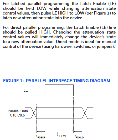
This should work okay. 7 data bits plus a latch, so all 8 pins used. If you just want to experiment then all three methods of wiggling pins in DIO should work.
a/A/@ commands for manipulating pins low/HIGH/input: a 0
a./A./@. bus commands for the same, but run in order: > a.0 a.1 A.2
0xff 0x00 bus data command for setting all 8 pins at once: > 0xff 0x00
Here’s how I’d start, with IO0-6 as data, and IO7 as latch:
> - tells the Bus Pirate we want to send data to the bus (and the bus doesn’t have a natural START/CS/RESET done with [, as is the case here)
a.7 - take pin IO7/latch low/ground
0x0F - load desired parallel data value on the pins, with bit 7 set to 0 keeping latch low. You can also do this in binary and it aligns with the table in the datasheet: 0b00001111 = 0x0f
A.7 - take IO7/latch high
a.7 - take IO7/latch low again. (Sorry didn’t catch this on the first pass)
The second option with LE just held high would be a bit easier to work with, but then you need to keep bit 7 high when you send values:
> A.7 //hold LE high
>0b10001111 // 0x0f with bit 7 keeping latch high