This topic primarily covers my review of how to use the RP2350 OTP area. It will document my attempts (and failures, and thus learnings) while going through the process. I’ve already got some neat hacks that are applicable, too.
I will keep things relatively short-looking, by lots of use of the details tag, so larger text blocks are collapsed by default.
It’s a fair enough question. First, allow me to recall some history of the BusPirate5 saga.
Rev8 vs. Rev10
BP5 has early version (known generally now as “Rev8”), which had some different hardware … including an SD card instead of onboard flash. Later, this was changed in “Rev10” to have onboard flash, and some pin mappings were changed. This raised a problem … how to determine if a firmware was accidentally applied to the wrong board type?
To be fair, Ian found a way to detect this, and the detection occurs early enough in the boot process that hardware should not be damaged. But, it would still be preferable to have a way to identify the specific model.
Manufacturing Glitches
At various times, there were problems in production (or caused during shipping) which only appeared once the boards are in customer hands. Much time was spent tracking down which boards had the problem, with the hope of tracking back to see if there was a common cause (e.g., all made on the same date? same batch?) It would be nice to have human-readable information that can be used in an error report to help correlate these issues.
Recall-like information
Having manufacturing information is also good for the customer. One issue (E9) affected all boards manufactured before a given date. How can a user know when their board was made? Ian and friends did a great job looking things up for folks and answering individual questions … but having it accessible (even without any firmware loaded) would be even better.
More Polished User Experience
The UF2 bootloader is drab. Every device out there using the RP bootloader seems to show the same “RP2350” volume, and the device advertises itself as Raspberry Pi’s product … not a BusPirate product. The INFO_UF2.TXT indicates only that this is a “Raspberry Pi RP2350”, of model “RP2350” … not a BusPirate. Worse, the UF2 bootloader has a HTML site that loads Raspberry Pi’s website. That should go to BusPirate.com, obviously
Can it be better?
The loaded firmware is already full controlling what is exposed over USB. Only the bootrom’s (and thus UF2 partition and behavior) were locked to the above behavior.
Wouldn’t it be even better if the UF2 booloader showed information more appropriate to the actual BusPirate product? YES!
New to the RP2350, there are now settings in the OTP area specifically set aside to provide richer customization of the UF2 bootloader.
I’ll walk through the details on how later, and a full walkthrough of changing things to meet some desired changes as an example.
For this example, at least at the time this post was authored, I am going to try to modify the bootrom to have the following changes (vs. the stock RP2350 bootloader behavior).
Vendor IDs and Product IDs should refer to the Bus Pirate board. So should the model information. The UF2 volume should have a Bus
Pirate based volume label. The UF2 volume’s text files should point to the buspirate site (for index.htm) and include both model and manufacturing data.
Changes from default bootrom?
USB_VID / USB_PID become 0x1209 / 0x7332
this is a value that Ian already has assigned to the BusPirate product (for the logic analyzer). Since the LA is now integrated, the PID is free to re-use here. Ian might obtain an additional VID/PID, of course…
UF2 Bootloader v1.0
Model: Bus Pirate 6
Board-ID: Rev0      LineA               20250214T012759Z
That last line deserves an explanation…
The first ten characters are reserved to store a revision identifier. This would correlate to BP5’s Rev8 vs. Rev10. The new BP7 might store “Rev0” on the first prototypes.
The next twenty characters are manufacturing information. I just put “LineA” as an example. Other values are expected.
The last bit is the ISO8601 string for the date of manufacture, as accurate as the factory processes allow. Maybe it’s the time the OTP is programmed.
Regardless, it’s just an example of three types of useful information that really should be exposed: Board hardware revision, manufacturing trace data, and datetime of manufacture.
Even better:
Program the serial number and a digital signature over the OTP settings & device serial number, and include that signature as an indicator of hardware sourced from DangerousThings / BusPirate.com / DirtyPCBs / Ian. Now the device can self-report with a higher degree of confidence a source of who made it. Missing or no signature just means no validation of the source … all functionality remains.
When this investigation is complete, I hope to have a working solution for programming the BusPirate 6 with the example data. This solution should even be usable on devices that are already shipped to customers (datetime would obviously be estimates, under customer control). If digital signature applied, however, Ian could provide estimates that match his needs (e.g., even approximate month might be good enough).
The only variable portion is the board revision / manufacturing string, so it should be relatively straightforward to move to production.
Since this is testing the bootloader, a PICO board is sufficient for testing … no need to do early tests on expensive hardware.
Simplifying things, one can think of the OTP as being an an array of uint16_t. Reading is done by a row address, which mentally can map to the array index of the uint16_t array.
Addressing Details (if you want them)
OTP addressing is … a bit weird … because of the options it supports. Each row of OTP is 24 bits. Generally, each row stores two bytes of data, plus one byte for ECC and polarity reversal protection.
Raspberry Pi made a choice to allow reading the OTP in multiple modes via alias’d addresses:
Read 32 bits of ECC corrected data corresponding to two neighboring rows.
Read 32 bits RAW from a single row (most significant 8 bits zero)
As either of the above, but using the now infamous “guarded” reads
Since these return different quantities of data for a single row, the API is based on a Row address, rather than byte offsets (which would change depending on mode).
Relevant Layout Details
OTP has 8192 bytes total, row addresses 0x0..0x0FFF.
OTP is then logically grouped into 64 pages, each 0x40 Rows (128 ECC corrected bytes).
Each page can be locked (various options… ignored here)
Of those 64 pages, six are not usable to store the customization data:
Page 0 is locked during manufacturing (0x0 .. 0x3F)
Bit 22 indicates the USB_WHITE_LABEL_ADDR field is valid
Each of bits 0..15 indicate a given field in that pointed to structure contains valid data. For example, bit 0 indicates if the USB Device Product ID field is valid.
OTP Row 0x05A USB_BOOT_FLAGS_R1
Redundant copy of 0x059.
OTP Row 0x05B USB_BOOT_FLAGS_R2
Redundant copy of 0x059.
OTP Row 0x05C USB_WHITE_LABEL_ADDR
Row index where the start of the “White Label” structure are stored.
(varies) USB_WHITE_LABEL
Conceptually, this can be thought of as the following C-struct:
The string reference values stored in the USB_WHITE_LABEL structure can only point forward, and can point forward a maximum of 255 rows. Thus, the strings to be used must be stored after, but close to, the USB_WHITE_LABEL itself.
It is not clear yet in which order to store the individual characters in a given OTP row.
Hacks
Because the STRING_REF is a counted (not null-terminated) string, a string that is a sub-string of another string may be directly referenced, so long as the starting point in the string is an even offset (for ASCII). It’s always possible to do this for unicode strings.
e.g., If storing “Bus Pirate ABC” and “Bus Pirate”, both STRING_REF can point to the start of “Bus Pirate ABC”, the second will just indicate fewer characters are used.
I will use this later to reduce the number of rows needed to store the strings.
UF2_INFO_BOARD_ID = “Rev 0 LineA 20250214T012759Z”
Just the strings …
There are only a few strings that need to be written to the OTP.
String
chars
rows
RowOffsets
Hack?
Bus Pirate 6
0x0C
6
0x10..0x15
Re-use
Bus Pirate
0x0A
5
0x10..0x14
BP6_BOOT
0x08
4
0x16..0x19
https://buspirate.com/
0x16
11
0x1A..0x24
buspirate.com
0x0D
7
0x1E..0x24
Re-use
Bus Pir8
8
4
0x25..0x28
Rev 0 ...
40
20
0x29..0x3c
Total Rows
0x10..0x3c
The second string re-uses the same OTP rows used for the first string, just fewer characters. For the fifth string, it’s just lucky that the https:// is an even number of characters, allowing to point a few OTP rows into the middle of that string for just the hostname.
NOTE: None of the data in this section should be presumed valid. It’s entirely untested, just the output after review of some documentation. Reality may differ.
One goal is to ensure everything fits in a single OTP Page (0x40 Row addresses). Keeping stuff aligned with OTP pages avoids contention with the lock bits and similar permissions. This also would mean that single page could be locked, to prevent any additional bits from being inadvertently set. Using the last usable page (0x60 … starting row of 0xF00) might also be preferable.
Row address offsets 0x3d, 0x3e, 0x3f are reserved for future use. Thus, the total size of the white label data is 0x40 rows (128 bytes).
Program Ordering during testing
Program the USB_WHITE_LABEL data + reference strings @ starting row 0x100 (0x100 .. 0x13C, inclusive)
Program the USB_WHITE_LABEL_ADDR to point to 0x100
Program the USB_BOOT_FLAGS to indicate which fields of the USB_WHITE_LABEL data should be considered valid.
0b_0000_0000_0100_0000__1111_0111_0011_0011
bit 0: USB VID
bit 1: USB PID
bit 4: USB Manufacturer string
bit 5: USB Product string
bit 8: Volume Label string
bit 9: SCSI VID string
bit 10: SCSI PID string
bit 12: Redirect URL string
bit 13: Redirect name string
bit 14: INFO_UF2.TXT model string
bit 15: INFO_UF2.TXT Board ID string
bit 22: WHITE_LABEL_ADDR is valid
0x0040F733
Test with this configuration
HACKHACK. If somethings not working, can still get three more tries on this same hardware. Re-write the USB_WHITE_LABEL starting at the following starting row addresses (once per attempt, in order), and then update USB_WHITE_LABEL_ADDR to add the bit needed for the new row address.
0x300
0x700
0xF00 EDIT: Oops … I forgot about the ECC. It might be possible to get more than one try, but doing so would require finding a first lower encoded address with few ECC bits set, and then a second address with more bits in both address and ECC (and none of the existing bits of the first address or ECC cleared). Glad I ordered a bunch of pico boards…
After those four attempts, if it’s still not working, disable the chip via the RMA procedure / decommisioning procedure (sets a bit in last OTP page…). Try again on a new chip…
When I build the BP6 board, I set it to download the PICO SDK (rather than installing it). However, it seems the picotool I end up with doesn’t have many of the OTP-related commands. I also have not found an official release point for just the picotool executable for Win64 (native). Sigh… I hope that doesn’t become the blocking factor. I may need to install a separate WSL2 distribution, just to let the SDK mess it up (but result in my having an updated picotool).
If anyone else wants to brick their devices, nothing here requires a BusPirate … a RP2350 Pico would work just as well. In fact, I have a stack of ten coming … for the explicit purpose of burning while I try some of these ideas. If you try some of this anyways, do share your results!
OTP doesn’t mean it is only write-able once, it means it can be made read only by burning bits in the last two pages?
If this is true, " If somethings not working, can still get three more tries on this same hardware" does this still apply?
There is an example of reading and writing OTP (and corrupting it) in the SDK. Shall I make this into a global command so we can poke around at it without PICO tool?
picotool seems like the efficient/proper way to do large manufacturing programming of OTP especially with signed/serialized stuff. However, you probably know by now that I loathe PC crapware for exactly the reasons you’re experiencing.
I can add that example as a global command and we can work it into a otp read/write/protect (maybe) tool. It will work the same way in 15 years as it does now
I’m going to be a little slow over the next few days (spring festival), but I’ll try to get a basic command pushed shortly.
When I’ve done stuff like this, OTP (when there’s room), I’ve stored an x509 cert.
You can encode your custom stuff in the extensions as bitstrings. The added bonus is it could be signed with Dangerous Prototype’s private key as a “genuine” product. Again, no loss of functionality if not.
There would have to be cert generated for each BP during manufacturing. It could be done as a step in test or initial firmware load.
Just a thought. There’s absolutely nothing wrong with what you’ve laid out and suggested; just an alternative. My most recent experiences with this sort of thing is using certs; but then again I was in a world where IEC 62443-3 and -4 was a requirement.
There is a new global command called otp that simply runs the PICO SDK demo for now. I have not tried to run it yet.
It is built on the dummy.c example command, and I left in the example boilerplate stuff at the very bottom for cribbing command line parsing and other common tasks.
No, I would not add OTP programming as a base command; It’s quite complex to get right, set appropriate boundaries, etc. Let it remain a distinct tool. That said, simply dumping the current OTP values is fine. Maybe also soft-lock the OTP early in boot (write to registers that prevent OTP modifications)?
Digital signature – Let’s split discussion of the digital signature options to a new thread. It’s interesting, and there’s many, many questions there; would be a pity to lose that in my wall of text on white labeling.
Yes, precisely. First, at boot time, soft-lock the OTP registers.
Then, read-only access to those registers is / should be allowed / safe. I can imagine a command that interprets the pre-defined fields, dumping them to JSON, and/or allowing dumping an arbitrary set of user-defined rows.
The arbitrary reads could even follow the basic BusPirate script format for reading.
Presuming it’s the same, has anyone compiled picotool themselves under WSL2, and is then able to use option to get information from a connected device?
~/bp5$ ./build_rp2350/_deps/picotool/picotool version
picotool v2.1.1-develop (Linux, GNU-13.2.0, Release)
~/bp5$ ./build_rp2350/_deps/picotool/picotool help otp
OTP:
    Commands related to the RP2350 OTP (One-Time-Programmable) Memory

SYNOPSIS:
    picotool otp list [-p] [-n] [-f] [-i <filename>] [<selector>..]

SUB COMMANDS:
    list   List matching known registers/fields
It’s reporting its version as v2.1.1-develop. However, according to the release notes, there were many picotool otp subcommands added in v2.0.0 … so where are they?
[[Edit: Grrr… found a note that says everything device-related is silently left out of the binary if packagelibusb-1.0-0-devis not installed. That’s terrible UI … they should list the additional options, with an error indicating that the build excluded those options, and how to fix it. Trying again… and if it works, will update buspirate docs to indicate folks should also includelibusb-1.0-0-dev.]]
[[Edit: Nope … installinglibusb-1.0-0-devdid not result in picotool having the device-oriented options. Frustrating…]]
I’m sorry, I have compiled picotool on WSL a few times, but I have never tried to connect it directly to a device. A single function (rom_func_otp_access) in the SDK reads/writes to otp and it is pretty easy to use. Might be easier than fighting the picotool, it sounds like otp isn’t enabled by default?
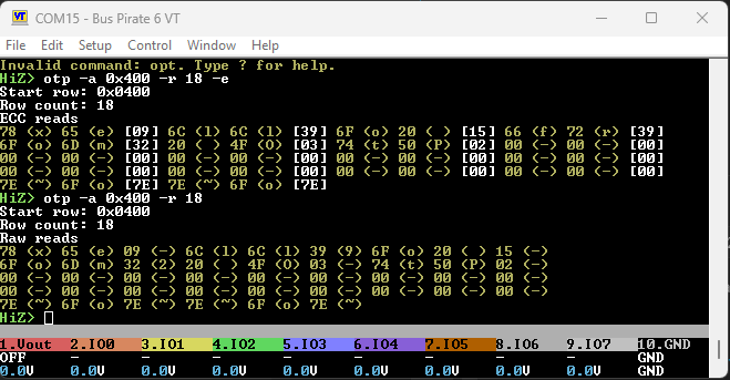
Updated otp command pushed, so at least we can explore the data.
otp -a <address> -r <number of ROWs to read> -e <highlight ecc bytes> -s <search for non-blank rows>
There seems to be a logic error in the number of rows dumped (and addresses) without the -e (raw mode). Don’t trust it. -e appears to be correct though.
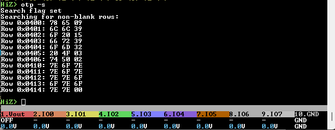
The search function loops through every row and reports non-zero rows. I ran the demo so I have some rows used now, they show up.
However, I assumed there would be manufacturing data in the first couple rows and some lock rows set, but I can’t see them. Maybe they are read protected state?
Thanks, Ian! I used this as the basis for a slightly improved OTP dump option. In particular, I noted the following problem with the read-only memory-mapped OTP ranges:
The bootrom API appears to allow reading an odd row, and only that odd row.
Reads of an OTP row in raw form often showed bit errors.
Reads of an OTP row with ECC correction did not have a reliable error indicator (check value is 0xFFFFFFFFu … which is valid!), nor did it have a way to indicate which row of the two rows even had an error.
My learning from this:
When allocating OTP for own use, ensure to allocate OTP rows in pairs (always 32-bits at a time).
Warning:
The docs indicate a neat hack for allowing the OTP to have a single-bit manufacturing flaw per row. If the hardware detects that the OTP row has exactly one bit flipped (impossible for correctly ECC’d row), then when writing to that row, it might store the inverted value (so the already-flipped bit can be read as either zero or one).
Soft-locking the OTP
For safety, I think it have soft-lock’d all the OTP bits early in boot. Makes it much safer to code OTP functions when you don’t have to worry about setting the wrong bit and thus burning rows…