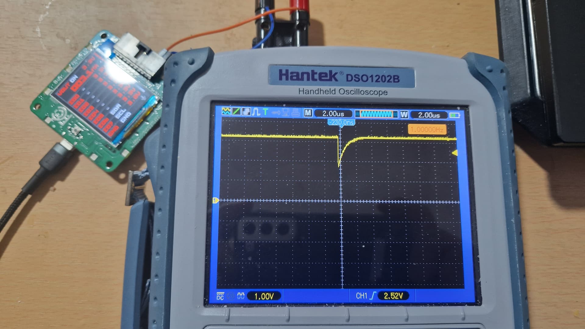
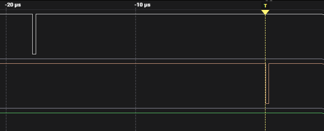
There is a 1 second periodic glitch (200ns wide) on both SDA and SCL lines for I2C mode with 10k pullups enabled.
Glittches presence does not depend on supply current limit. Tested for 3v3.
1 Like
before researching this, one important question:
Is your logic analyzer built using comparators instead of standard CMOS buffers? Minimal hysteresis could cause glitches, especially with slow rise/fall times at the comparator threshold. This is often seen in I2C, where pull-up resistors affect rise/fall times. Many logic analyzers incorporate a glitch filter to address this issue.
Hi Dreg, I can clearly see these glitches both on 200Mhz oscilloscope and all logic analyzers I have (testes with 4 different L.A.-s). Glitch filter must be available for the trigger of the logic analyzer not just for the captured signals in order to adress such an issue.
If you see the glitch with the oscilloscope, it’s more concerning. Thank you for clarifying this point.
Hi kokoshell,
Welcome to the forum, and thank you so much for the bug report.
How could I reproduce this glitch? Would it be possible to post a screenshot of the logic or oscope? Edit: Does it just glitch while sitting there every second? Pins go to wrong state?
Here’s some places I’ll check when I know how to reproduce it:
- Syntax execution
- I2C PIO - there was (is) a bug several people have found in the I2C pio example in the PICO SDK that make it unusable. I applied the fix, but it could have knock on effects.
- USB and LCD are handled from a different core than syntax execution, so I don’t think they’d interfere. However the RGB LEDs are on the same core and do interrupt. I’ll move that to core 1 too, but it will take a bit of finagling to get it done. Just in case, I’ve attached a firmware with the LEDs disabled.
bus_pirate-noleds.zip (114.6 KB)
Cheers,
ian
Hi Ian,
Yes its a permanent periodic glitch on SCL and SDA (1 second period) with 10k pullups enabled
1 Like
Thank you so much, that is very helpful.
I see it on I2C here.

On an unused pin here too.
I did a check of the PSU output and fortunately did not get a trigger there, but the equipment I have on hand at the moment is limited.
If it was every 500ms I would suspect a issue with the way I’m currently driving the analog mux (set to ground, then measure from pins).
Further investigation:
- Test with AMUX disabled
- Enable additional pin pull-down on I2C buffer (we manipulate the direction, not state)
I will update when I have more info.
Thank you again for finding this bug and the additional info!
EDIT: I disabled the analog mux that measures voltages on the pins, the glitch is gone. Since I didn’t see this during the initial two rounds of I2C debugging, my guess is it has to do with the timing updates I made to the voltage measurements for the final revision. I’ll update shortly, curry just arrived ![]()
This seemed to fix it for me. It’s not a final solutions, but that seems to be the bug.
bus_pirate-amux-timing-update.zip (114.9 KB)
1 Like
Glitch is gone thank you Ian! ![]()
1 Like
Hi Ian, noticed that in the timing update you moved I2C lines on IO0(SDA) and IO1 (SCL) closer to VOUT … Is it going to be permanent ?? Really dont want to see someone using by mistake VOUT (3v3 enabled !) taken for SDA line on a 5V board with strong pullups ![]()
1 Like
Thanks for the update! And thanks again for the bug report, I really depend on them because the project is so large.
Here’s a second test with tighter timing:
bus_pirate-amux-speed-test-2.zip (119.3 KB)
Summary:
- In the beginning I had to use really long delays between switching AMUX channels or there would be “bleed through” from high to low pins (showing wrong voltage). I assume this is switching speed of the 74HT4067 and capacitance on various pins.
- I started switching the AMUX to a grounded pin between each change of pin, this eliminated the need for a delay.
- However, for REV9 I switched to a Chinese made, improved CD4067 (Wuxi I-Core) with much faster switching speeds (better supply and WAY cheaper). That is where I did the testing when I tuned the timing.
- I assume what we’re seeing is the switching speed difference between the Infineon 74HC4066 and the I-Core CD4067, because I could not initially reproduce this bug on REV9. I will continue to work with REV8 now so there are no more missed issues like this.
- This test firmware uses the “ground between channels” hack, but fiddles with the delays a bit and gives it more time to settle before changing among channels.
Other bugs:
- I noticed the I2C speed setting isn’t being put to the PIO module. It just runs at 100khz. It is on my list to fix.
Other fixes:
- Fixed the bug where the syntax compiler doesn’t report slot overflow (thanks @dreg!)
1 Like
That’s a really good point and sensible design approach.
Eventually the pin position can be selected by the user. This was the original position and I promised DREG I’d put them back ![]() I’m triaging a production emergency this afternoon, but I’ll make pins select-able ASAP.
I’m triaging a production emergency this afternoon, but I’ll make pins select-able ASAP.
I’m not sure about the 5V board, but the Bus Pirate should itself be pretty immune to this kind of situation. The IOs are all 5.5v tolerant and have partial power down. The PSU has a “one way” valve that prevents any backflow when the voltage on VOUT/VREF is greater than VOUT.
Since the bug crept back and I found other ways to trigger it, I need to do some intensive testing.
I’m concerned that there’s some in-rush current during switching. Both the 4066 (prevent back powering) and the buffer chip (prevent damage from shorts) have 330 ohm resistors, and this may be the issue ![]() It certainly looks like it from your oscope.
It certainly looks like it from your oscope.
I need to test more to see why I’ve not seen this previously.
Update:
I can reproduce the problem consistently on REV8. I cannot reproduce the problem at all on REV9. This doesn’t mean there’s no problem, I need to use a proper scope on Monday to look at both boards with the different potential solutions.
The difference between REV8 and REV9 (in this area) is only the parts: 74HC4067 vs CD4067 for the mux, and GS6001 vs LMV321 for the op-amp. I need to test REV9 to see if the problem is still there, but not to the extent that would trigger an LA.
I verified the timings in the datasheets and I don’t think extra delay is the issue. It certainly looks like there’s some inrush/capacitance happening when the MUX had previously selected a pin that was grounded.
I further verified that this glitch only triggers when using pull-up resistors. So, the issue is probably around whatever inrush current is happening when we open up the MUX through the 330R backpower prevention resistor and the 10K pull-up limits the current.
One thing I would like to test is the effect of using a 2K pull-up would have on the situation. I don’t have any non-0402 resistors on hand at the moment though.
Checking through the datasheets, the op-amps are very similar and both have 1pA bias current on the inputs, so very high impedance. The MUX have 0.1uA leakage at normal temperatures.
Separate issue: the 74HC4067 has +/-20mA input clamping, while the CD4067 has +/-10mA. We need to add a bigger current limiting resistor to the MUX inputs to prevent damage during back-powering. That may or may not be a useful change. I need to find the simulations and run them again.
I’m really thankful for your report, this is a bug that needs to be dealt with ASAP.
1 Like
Confirmed the glitch on all hardware versions. It has a different shape with the Wuxi I-Core chip, but it’s still there.
I’m going investigate how to add op-amps to the 8 IO pins in front of the mux. Problems:
- Op-amp needs protection for partial power down, if something powered is connected but the Bus Pirate is not powered.
- Board space. Where to put them is going to be an issue.
If anyone has any suggestions I’d love to hear. I’ll begin by studying some oscope front ends because this must be a problem they have to address.

After some review, I think I have a quick and dirty fix.
- We’re going to add 8 op-amps (LMV324 x 2) to buffer the IO input to the MUX. The op-amp can go 0.5V from either rail.
- To protect the op-amps if there is an outside voltage when the Bus Pirate is powered down, we’ll add schottky diodes behind a 10-100K-ish resistor. that will limit the voltage on the op-amp to 0.3V, while also dumping to the VUSB power supply. Dumping to the power supply will also power the op-amp and help keep it safer.
- This will also help address the back power issues. We’re currently protecting with series resistors on pins that can be back-powered and keeping it within the limits of the MUX pin diodes. This is a much better solution though.
1 Like
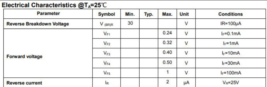
BAT54 from my favorite die-bonder, CBI. They have amazing customer service, I’ve ordered reels late on Sunday and they always have someone available.
With a 10K current limiting resistor we’d have 0.5mA current at 5 volts. The BAT54 forward voltage is max 0.32volts @1mA.
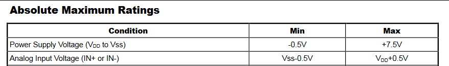
LM32x from HGSemi. I’ve used their chips in prototypes, they seem like a small competitor to WuXi I-Core, but I’m almost certain they just bond the same die fabbed by a third party.
Maximum input is +/-0.5volts from the rail, 0.32volts should be fine with some margin for temperature differences.

LTSpice Simulation of new front end with direct and pull-up IO styles.
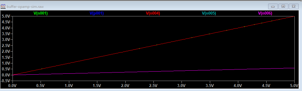
Looks ok.
buffer-opamp-sim.zip (659 Bytes)
1 Like