Can I/ will I be able to program a PIC or Atmel microcontroller with a Bus Pirate 5. Thanks.
1 Like
Not yet.
Binary mode should be done this week, then we can start porting programming apps.
Which chips do you want to program? Some pics for example need a 13V VPP, which will require an external supply and FET.
I work with mainly PIC16F and PIC18F series that are programmed using the PICKIT5/ICD5. If an external supply and FET are needed could that be provided for with a plug in board of some kind?
Haha! yes, that would be a nice little project and useful for other chips. Your 16Fs and most 18Fs(?) will need 13volts on VPP/MCLR (?) to enter programming mode (its been a while since I’ve used them).
A small boost converter with up to 17 (?) volts output using a PWM and ADC pin from the IO header, and a 3rd IO pin for switching VPP. I will sketch something out.
1 Like
Are you aware of this open source PIC programmer?
You may be able to adapt the hardware and code as needed. If you go to the github repository someone has done an SMT version of the hardware in Kicad format.
Alberto Maccioni (the original creator) is also very helpful on the support forum.
Thanks.
1 Like
Good Link! Thank you! That will make things a lot smoother.
Something like this should work. I can make it a plug in adapter, with a second 10P header so it works with the Bus Pirate cables and stuff.
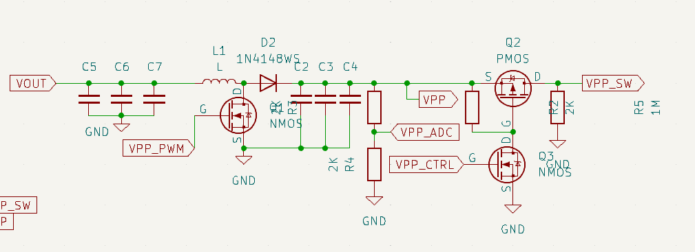
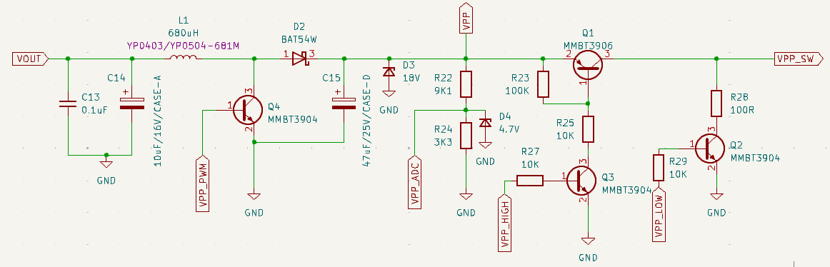
PWM from Bus Pirate drives a boost converter. Feedback is through a resistor divider to the BP ADC. Some sort of high side switch enables/disables VPP.
The NFET/PFET pair may not be needed at <40volts. Lately I’ve been doing very small voltages, instead of very big voltages. That’s how my last nixie tube driver was designed, but I need to look at PFET datasheets.
The best idea is probably crib the values and switch design from a pickit schematic, just to do it the professional way.
A nice thing about this design is it has no clock, so it doesn’t have to be FCC certified strictly speaking.
1 Like
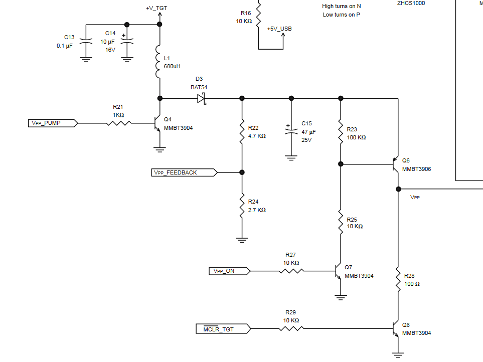
This is the pickit2 VPP system, I routed this onto small board. A few tweaks (and sourcing) are needed before I test it.
1 Like
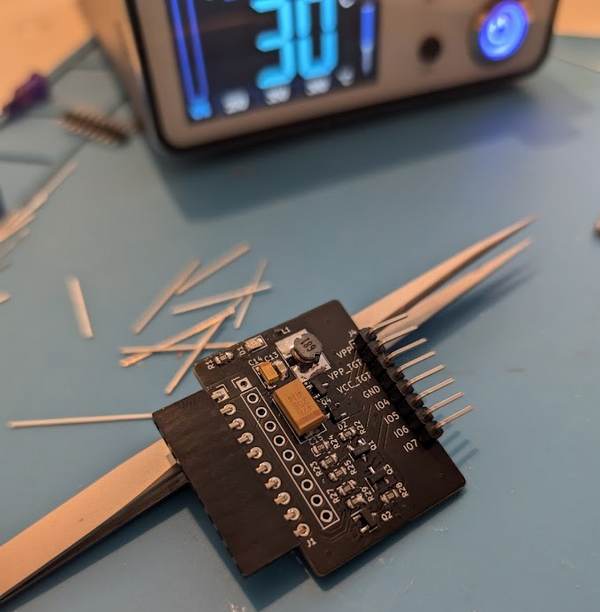
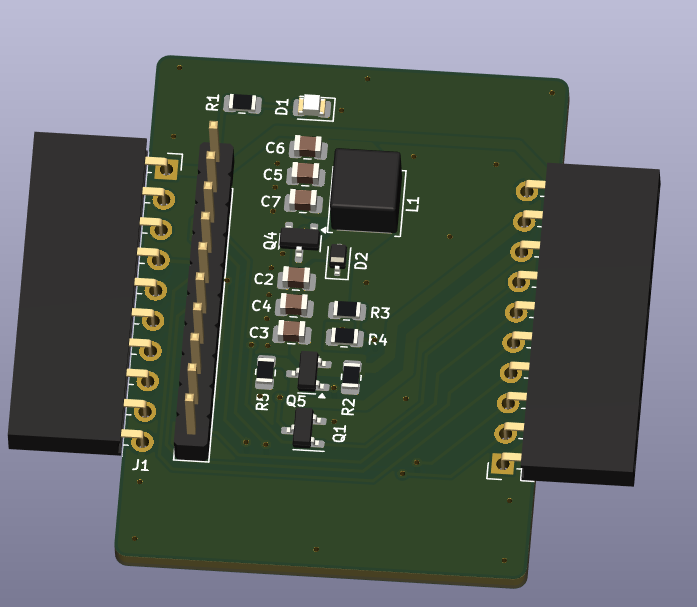
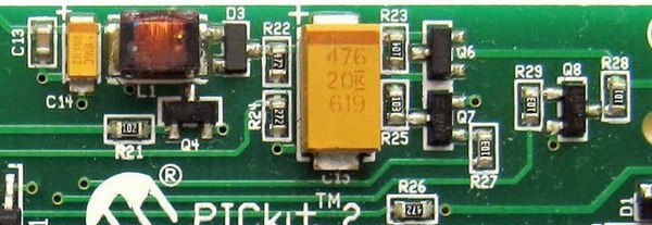
Some progress on this one. PCBs arrived and I stuffed them this morning. The final design is an exact copy of the PICkit2 SMPS.
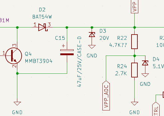
Output voltage is measured through a 4.7K/2.7K divider, which hits 4.75 volts at 13volts output. This is perfect for a PIC, but I feel like we should target 5-20 volts output.
Anyone familiar with any VPPs? PIC16/18F is 13volts. Someone asked a question in the forum about something that needed a 7volt VPP. Looks like AVR uses 12.5volts, and some EEPROM need 12 for programming and 14 for erase.
According to the Chaotic Shambles of EEPROM Voltages vintage chips may need up to 26volts. That may be a bit much.

The big output cap is rated for 25V and costs more than $0.50 (using genuine Kemet/AVX), a bigger cap will cost even more.
One tweak I want to make in the final board: a 20volt zener diode on the output (D3) in case of failure. Also a 5.1v zener (D4) on the feedback to the Bus Pirate ADC. Something to keep the output caps within limits and avoid damaging the Bus Pirate.
3 Likes
SMPS board up and running, with some zener diodes to protect everyone.
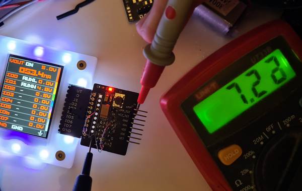
Started an smps command that handles PWM and feedback loop to set the output voltage. Set to 7volts output in the photo.
- Big current spikes - Makes sense with the inductor and unaveraged current measurements, but still higher than I would expect. Need to investigate this.
- Inductor gets warm. Pretty normal in an SMPS, but at no load and only a 2 volt boost I suspect the inductor is not fit for this application. Probably related to the previous point.
Ah, I think the PWM isn’t settling at ground when I skip pulses to maintain the voltage. Maybe the counter should be set to 0 instead of disabling the PWM.
Also, the frequency is very low (10khz), 50khz is what I usually use.
Feedback resistors
Designing for 18V maximum output:
- 20V output protection zener diode has a range of 18.8…21.2 V
- 4.7V feedback protection zener has a range of 4.4…5 V
- Lets assume a 22V output measurement max
- Lets assume a 4V feedback measurement max
- 10K/2.2K divider give us 3.97V feedback @ 22V ouput
That’s a little tight, maybe 14-16V output is a better goal. First to get it working well though.
3 Likes
Thanks for all the work you are doing on this. Will this work with low voltage programming, which is what I mainly use with the PIC16F/PIC18F? I use the ICD3 and PICKIT 4. I don’t think it uses high voltage mode when I use it. Thanks.
Yes, absolutely. I’ll implement a hardware interface for the open source pic programmer software, so it should support everything it does.
4 Likes
Our previous design just wasn’t working out. I copied exactly the pickit2 SMPS layout and hopefully this one doesn’t get as hot.
3 Likes
Look at the large copper area under L1 on their board… is that the part getting hot?
I mixed up which is which… Nicely done giving it a solid heatsink. ![]()
The previous version was much more professional with nice zones and such. The latest is my hack-job copy of the pickit ![]() Though upgraded with some sensible protection for hardware and humans.
Though upgraded with some sensible protection for hardware and humans.
2 Likes
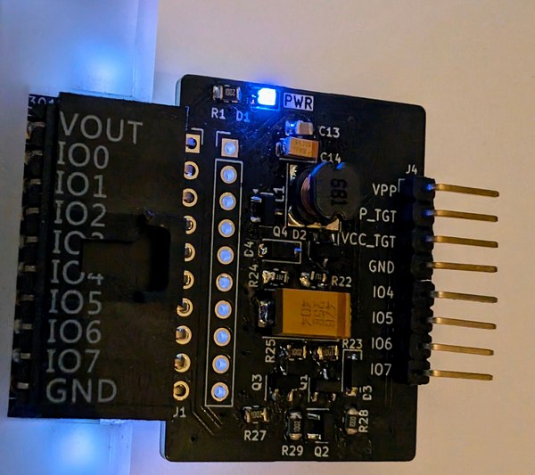
The latest VPP maker board arrived this week and I stuffed it. The good news is it no longer gets hot and the regulation is improved. Still seeing current spikes, but need to investigate further with a scope.
Output (limit)
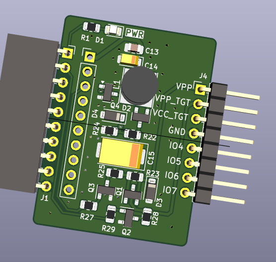
VPP maker is a bare bones Switch Mode Power Supply in a boost mode configuration. We take the ~5volts output from the Bus Pirate and boost it to 5.1-16volts.
16volts output is a good maximum limit. It covers just about every programming voltage except some rare antique EEPROMs/PROMs.
C15 is a big 47uF tantalum capacitor that stores and smooths the SMPS output. It should be rated for 150% of the maximum output (or 200%). 25volt rated tantalum capacitors are available in a fat case-D package and cost about $1 each. Higher voltage rated versions get fatter and more expensive fast - another good reason to target 16volts maximum output.
To protect the SMPS components, connected devices and humans, a zener diode (D3) is connected from the SMPS output to ground. If the voltage gets too high, the zener conducts to ground. There’s no protection resistor so in the worst case scenario the zener burns out “open” and shorts the SMPS to ground. The board will be ruined, but it will prevent runaway output.
Cheap zener diodes have pretty sloppy tolerances. The lowest tolerance of the zener should be just a tad higher than our maximum output of 16volts. An 18volt zener starts conducting between 16.8 and 19.1volts, it should be about perfect.
Feedback (limit)
The Bus Pirate periodically measures the SMPS output voltage. If the voltage is too low, the PWM is enabled to drive the SMPS. If the voltage is too high, the PWM is disabled. This is the SMPS feedback loop.
16volts is too high for the Bus Pirate to measure directly, so the output is sampled through a feedback resistor divider (R22, R24). We never want the output of the feedback divider to be greater than 5volts (the Bus Pirate maximum IO voltage).
First, let’s choose a protection diode (D4). A 5.1volt zener might be the obvious choice, but as before, zener tolerances are sloppy. A 5.1volt zener starts conducting between 4.8 and 5.4volts. In the worst case just a tad too high. A 4.7volt zener starts conducting between 4.4 and 5volts. We lose some measurement range, but the maximum worst case scenario of 5volts is perfect.
The maximum feedback voltage is slightly under 4.4volts (minimum worst case of 4.4volts of the zener diode). I’ve chosen a 9.1K/3.3K resistor divider. At 16volts SMPS output the feedback divider will measure 4.258volts.
smps command
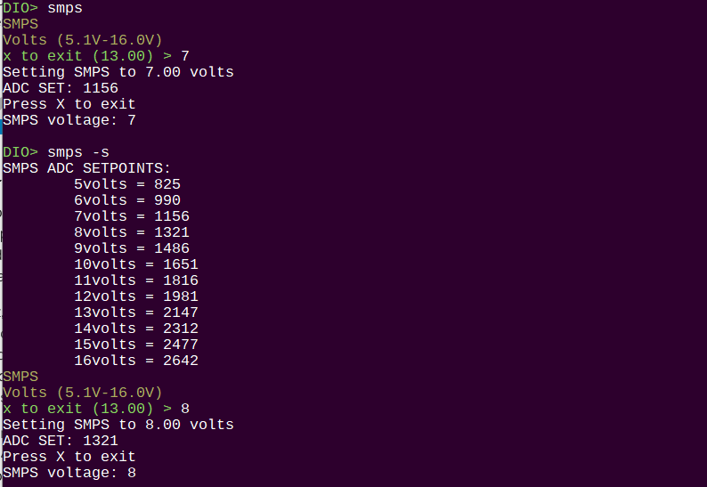
Long term there will need to be an interrupt or maybe there is a comparitor type setup that can gate the PWM during programming operations. For now, there is a simple SMPS test command.
- Enter a mode
- Enable a power supply
smps 15.5- set 15.5volt outputsmps -s- show calculated ADC set points (debug)smps- will prompt for the output voltagexto exit and disable SMPS
Enable the smps. It will calculate and show the ADC set point representing the output voltage. Every second the SMPS output voltage will be updated in the terminal.
Output is pretty accurate, but at some points is ~0.25volts off. I suspect there is a float handling issue somewhere.
3 Likes
@djsb did you manage to figure it out? I am in a need to reprogram this:
There is low voltage version (5V) but I was unlucky and I got 12V. Am I correct that with SMPS plank I will be able to reprogram it?
Hmm, what is the reason for designing your own boost regulator and not use some existing one and just adjust the feedback?
I imagine getting the software feedback loop working well is quite some amount of work. I did dabble in this area some years ago but the stability I could achieve was quite bad and slow compared to all integrated dc/dc regulators available. So I moved away from this design, even if it was more expensive back then. Now the integrated dc/dcs are cheaper in most configurations.
The MT3608 is a very common and cheap Chinese boost controller that could work well for this plank. It is easy to use, you just have to make sure to get the proper ones from Aerosemi and not some bad knockoffs. You could use a small I2C controlled DAC to control the output voltage. The DAC output goes through a resistor into the feedback input of the regulator, just like in the BP.
That might be a better approach. My first “real” project was a nixie tube thing, so I feel pretty confident rolling a boost converter. However, from a “mas produced” standpoint it is probably a better idea to use a dedicated IC.
For this version of the SMPS plank, my goal was mostly to have some kind of voltage source if anyone was interested in doing some old PIC/AVR/EEPROM hacking.
1 Like
The nixies have a pretty constant load and you just slowly change their output when you switch to a different number. This makes using a software-controlled feedback loop easier.
Digital circuits like microcontrollers to be programmed don’t draw much, but the current draw can change quite fast. So the regulation has to be fast enough to account for that.
Regarding a plank: you could make it even cheaper if you replace the I2C DAC with PWM, R/C-filter and a simple opamp. Also you could use smaller and cheaper inductors and capacitors due to the much higher switching frequency of the MT3608 (1.2 MHz).
3 Likes
@ian I just saw this topic (one of the bad parts of the new forum system for me). I designed an SMPS board for BPv4 back in the day and it also had a real simple control code for it (called skip pulse control). Maybe it’ll be useful?
HW should be this: Bus_Pirate/hardware-other/PiratePICprog at master · DangerousPrototypes/Bus_Pirate · GitHub
And code to control it is this file: Bus_Pirate/Firmware/smps.c at master · DangerousPrototypes/Bus_Pirate · GitHub
4 Likes