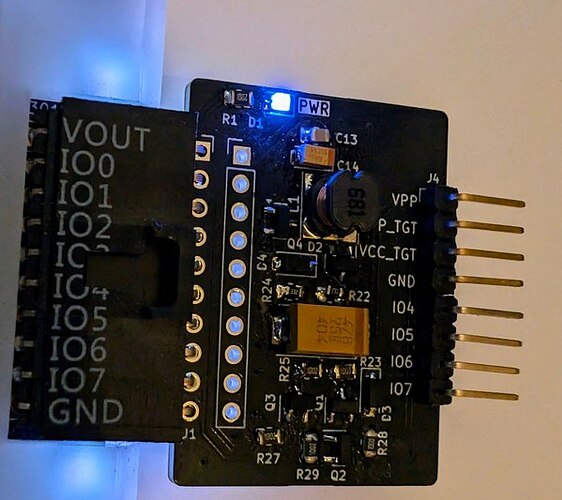
The latest VPP maker board arrived this week and I stuffed it. The good news is it no longer gets hot and the regulation is improved. Still seeing current spikes, but need to investigate further with a scope.
Output (limit)
VPP maker is a bare bones Switch Mode Power Supply in a boost mode configuration. We take the ~5volts output from the Bus Pirate and boost it to 5.1-16volts.
16volts output is a good maximum limit. It covers just about every programming voltage except some rare antique EEPROMs/PROMs.
C15 is a big 47uF tantalum capacitor that stores and smooths the SMPS output. It should be rated for 150% of the maximum output (or 200%). 25volt rated tantalum capacitors are available in a fat case-D package and cost about $1 each. Higher voltage rated versions get fatter and more expensive fast - another good reason to target 16volts maximum output.
To protect the SMPS components, connected devices and humans, a zener diode (D3) is connected from the SMPS output to ground. If the voltage gets too high, the zener conducts to ground. There’s no protection resistor so in the worst case scenario the zener burns out “open” and shorts the SMPS to ground. The board will be ruined, but it will prevent runaway output.
Cheap zener diodes have pretty sloppy tolerances. The lowest tolerance of the zener should be just a tad higher than our maximum output of 16volts. An 18volt zener starts conducting between 16.8 and 19.1volts, it should be about perfect.
Feedback (limit)
The Bus Pirate periodically measures the SMPS output voltage. If the voltage is too low, the PWM is enabled to drive the SMPS. If the voltage is too high, the PWM is disabled. This is the SMPS feedback loop.
16volts is too high for the Bus Pirate to measure directly, so the output is sampled through a feedback resistor divider (R22, R24). We never want the output of the feedback divider to be greater than 5volts (the Bus Pirate maximum IO voltage).
First, let’s choose a protection diode (D4). A 5.1volt zener might be the obvious choice, but as before, zener tolerances are sloppy. A 5.1volt zener starts conducting between 4.8 and 5.4volts. In the worst case just a tad too high. A 4.7volt zener starts conducting between 4.4 and 5volts. We lose some measurement range, but the maximum worst case scenario of 5volts is perfect.
The maximum feedback voltage is slightly under 4.4volts (minimum worst case of 4.4volts of the zener diode). I’ve chosen a 9.1K/3.3K resistor divider. At 16volts SMPS output the feedback divider will measure 4.258volts.
smps command
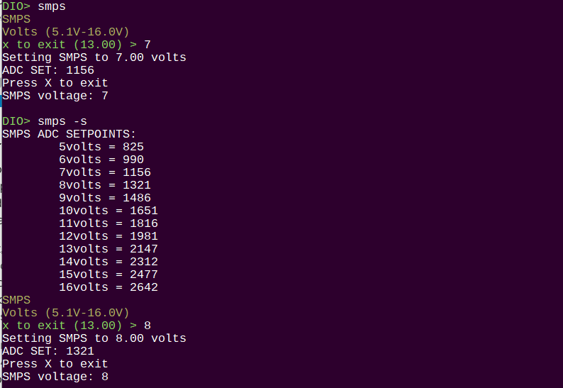
Long term there will need to be an interrupt or maybe there is a comparitor type setup that can gate the PWM during programming operations. For now, there is a simple SMPS test command.
- Enter a mode
- Enable a power supply
smps 15.5- set 15.5volt outputsmps -s- show calculated ADC set points (debug)smps- will prompt for the output voltagexto exit and disable SMPS
Enable the smps. It will calculate and show the ADC set point representing the output voltage. Every second the SMPS output voltage will be updated in the terminal.
Output is pretty accurate, but at some points is ~0.25volts off. I suspect there is a float handling issue somewhere.


