Porting DirtyJTAG

@phdussud made a RP2040 port of the STM32 DirtyJTAG project.

I’ve previously ported this firmware, but in a very messy way. My goals here are:

  1. Use the base /pirate/ library to control Bus Pirate specific hardware (perhaps as a submodule)
  2. Using a fork of the original repo
  3. Add the forked repo as a submodule of a “master” repo
  4. Build all the sub repos on the build server and give us some status info

The Pico Probe firmware port will come next as a test of 3 & 4.

3 Likes

In theory dirtyjtag is ported to the Bus Pirate, however USB is not connecting (device startup error)

  • Main branch of pico-dirtyjtag compiled for PICO board with 2 UARTs active works
  • Same with 1 UART active: lots of compiler warnings about descriptor size
  • Same with no UART active: seems to connect ok
#define CONFIG_TOTAL_LEN  (TUD_CONFIG_DESC_LEN + TUD_VENDOR_DESC_LEN + TUD_CDC_DESC_LEN * CFG_TUD_CDC)

#if ( USB_CDC_UART_BRIDGE )
    "DirtyJTAG CDC 0", // 4: CDC Interface 0
    "DirtyJTAG CDC 1"  // 5: CDC Interface 1
#endif

This seems to be the source of the compiler warnings. The total length takes into account the number of CDC interfaces, but then both are added anyways.

#if ( USB_CDC_UART_BRIDGE )
    "DirtyJTAG CDC 0", // 4: CDC Interface 0
    #if(PIN_UART_INTF_COUNT==2)
    "DirtyJTAG CDC 1"  // 5: CDC Interface 1
    #endif
#endif

This update removed the compiler warnings, but USB does not enumerate.

This is probably a me problem, I’ll continue to debug it.

1 Like
enum
{
  ITF_NUM_PROBE = 0,
#if ( USB_CDC_UART_BRIDGE )
  ITF_NUM_CDC_1 = 1,
  ITF_NUM_CDC_1_DATA,
  #if (PIN_UART_INTF_COUNT == 2)
  ITF_NUM_CDC_2 = 3,
  ITF_NUM_CDC_2_DATA,
  #endif
#endif 
  ITF_NUM_TOTAL
};

I missed one. Now it seems to work :slight_smile: Next I’ll get the display going with pin labels, then we can make an initial release.

Other ports to throw in the mix for initial testing:

  • Pico probe
  • GusmanB logic analyzer
  • pico-sdk-logicanalyzer (continuous sampling supported by pulseview)
2 Likes

Maybe consider yapicoprobe instead of Pico probe?

yapicoprobe is based on pico probe, but adds quite a bunch of features on top.

Also the author is looking for a better hardware than the regular pico, something with level shifters and a programmable voltage regulator:
yapicoprobe hardware.adoc
So maybe they are interested in helping to port?

2 Likes

@electronic_eel Sure, I’ll do that one.

DirtyJTAG is compiling and connects to USB. However, I get garbage from the debug UART. It also seems like the pull-ups are not enabled, and the LCD isn’t working at all. It looks find under debug (not crashing).

I think I pulled in too much Bus Pirate code at once. I’m going to start again with just the pin assignments and test it step by step.

2 Likes

I’ve been stuck on this for a couple days now.

The good news is everything seems to be working, the LCD, pull-ups, initial config.

However, whenever I connect to the CDC port I get something like this. I’ve struggled thinking this was something I pulled in from the “pirate-lib”.

#define PIN_UART_INTF_COUNT 1
#define PIN_UART0 uart1
#define PIN_UART0_TX    8
#define PIN_UART0_RX    9

Today I rolled back all my changes and tried plain firmware with a PICO using the same UART as the bus pirate (uart 1). Insight! It also bugs. So it’s not me.

uart_index = uart_get_index(uart_);
...
	for (size_t i = 0; i < PIN_UART_INTF_COUNT; i++)
	{
		uart = &uart_devices[i];

Can you see the bug? The array of two UART device structs is populated using the index of the uart (0 or 1). Later, we loop on the total uart count and get the unpopulated uart 0 config.

1 Like

Seems to be fixed with this pull request.

hopefully we have something usable soon :slight_smile:

Anyone out there with JTAG stuff to test?

Me me me! Cannot wait🥳

1 Like

DirtyJtag running on the Bus Pirate with pin labels and direction indicators.

dirtyJtag.zip (44.3 KB)

Note: You will need to apply the target voltage to Vin (Vout/vref) to power the buffers at whatever voltage the target is using

Here’s the firmware. I would greatly appreciate any testing as I don’t have a Linux computer or a JTAG target handy.

Up next:

  • Port yapicoprobe and see how reusable the new new new pirate lib is
  • Get everything set up in a central compile repo
  • Auto build everything and put that somewhere (github release?)
  • Page with list of ported firmware, what is does, where to read docs (at the github compile repo and in our official docs?)
5 Likes

dirtyJtag.zip (31.4 KB)

I don’t think there is any functional change here, but this firmware is updated to the latest commit on the forked repo.

2 Likes

Functional change or not. The lcd screen is black after flashing the last attached. Also there is huge size difference between files.

Firmware from previous post seems to work, at least it shows the same screen as the picture You attached. And UrJTAG doesnt complain when running “cable dirtyjtag”

So I’ve made some tests. Found out the TRST pin on target device. Shorted to GND and turned on device. Screen is blank at this point so this works. I’ve re-checked all connections 3 times with multi-meter and there is no shorts.

jtag> cable dirtyjtag
jtag> detect
warning: TDO seems to be stuck at 0

This is when device is not connected.

jtag> cable dirtyjtag
jtag> detect
warning: TDO seems to be stuck at 1

This when issuing detect command. Additionally device restarts in normal operation mode after sending detect. So probabbly it sends SYSRST/RST when…

jtag> cable dirtyjtag
jtag> frequency 40000000
Setting TCK frequency to 40000000 Hz
jtag> detect
warning: TDO seems to be stuck at 1

Setting the frequency to 40MHz results in the warning above. But the device doesn’t reset. I saw similar problems with libftdi driver for BusBlaster to note on some famous dangerousprototypes forum :wink:

Edit:

clock_gettime(CLOCK_MONOTONIC, {tv_sec=26566, tv_nsec=712387927}) = 0
timerfd_settime(4, TFD_TIMER_ABSTIME, {it_interval={tv_sec=0, tv_nsec=0}, it_value={tv_sec=26567, tv_nsec=712387927}}, NULL) = 0
ioctl(7, USBDEVFS_SUBMITURB, 0x55fb9f67ded0) = 0
poll([{fd=3, events=POLLIN}, {fd=4, events=POLLIN}, {fd=7, events=POLLOUT}], 3, 60000) = 1 ([{fd=7, revents=POLLOUT}])
ioctl(7, USBDEVFS_REAPURBNDELAY, 0x7ffe3fd145f0) = 0
timerfd_settime(4, 0, {it_interval={tv_sec=0, tv_nsec=0}, it_value={tv_sec=0, tv_nsec=0}}, NULL) = 0
ioctl(7, USBDEVFS_REAPURBNDELAY, 0x7ffe3fd145f0) = -1 EAGAIN (Resource temporarily unavailable)
write(2, "warning: ", 9warning: )                = 9
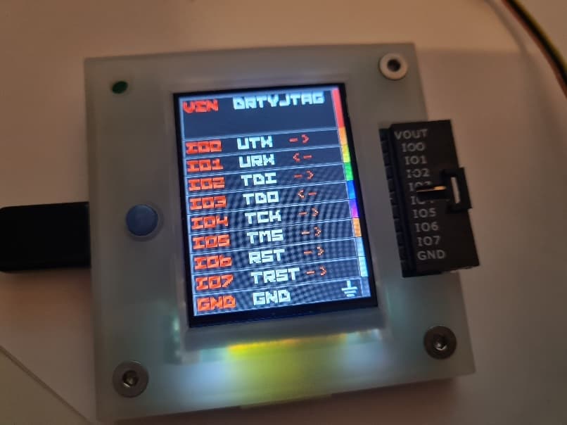
write(2, "TDO seems to be stuck at 1\n", 27TDO seems to be stuck at 1
) = 27

This is what I get when I run detect on urjtag with strace. I am particulary worried about:

ioctl(7, USBDEVFS_REAPURBNDELAY, 0x7ffe3fd145f0) = -1 EAGAIN (Resource temporarily unavailable)

But not sure now if it’s not trying to open other USB devices

Edit:
I think I will swap TDI and TDO maybe thats the issue here. But not today. Swapped there and back same results. Or once detect finished but no chip detected.

question. do you need to use a reset pin to get jtag to enable itself? i get these tdo stuck at 0 and 1 errors in my testing too, but then i found out i had a lead that had fallen off that would put the device into a mode that enabled jtag fully.

Well JTAG should work without chip being in Reset state. Yes.

Here is relevant schematix. Glad it leaked to the web.

And there is ICE Mode connector with ASEMDO pin that I jumpered to the nearby (just next to) GND. This trick according to some japanese website and Hardware Manual of the chip should enable JTAG function in general.

Edit: And well I couldn’t fuck it up here🤣 just goldpins soldered and physical jumper from middle (ASEMDO) to the right pin (GND).

I have two options now. Keep co-processor (DSP) in Reset state. To check if it contaminates bus. This will be done today (reguires soldering of gold pins again). And recheck. And if its not this then I think its a bug in DirtyJTAG firmware. If somone else (@ian did your target JTAG device arrived?) cloud check if one has some JTAG target.

Also I am noting it here. I checked continuity of the board few times as crazy to be sure all pins are ok and there is no short/leak and I do confirm physical connections of my adapter board are fine.

I’ve soldered two pins for TRST and GND for the co-processor (DSP) and now when it’s jumered I get this:

jtag> cable dirtyjtag
jtag> bsdl path /home/areyouloco/KORG_ESX_EXM_REVENG/
jtag> frequency 25000000
Setting TCK frequency to 25000000 Hz
jtag> detect
warning: TDO seems to be stuck at 0
jtag> detect
warning: TDO seems to be stuck at 0
jtag> detect
warning: TDO seems to be stuck at 0
jtag> frequency 40000000
Setting TCK frequency to 40000000 Hz
jtag> detect
warning: TDO seems to be stuck at 0
jtag> detect
warning: TDO seems to be stuck at 0
jtag> detect
warning: TDO seems to be stuck at 0

I had a heart attack moment. because it didn’t want to turn on correctly after DSP in Reset state but now it’s fine.

I do not have my target board yet. Do you have LA or scope to see if the pins are actually wiggling?

I have some LA I could solder pins next to BP connector. But the problem is… yeah whatever I will just install again DSView (chinese stolen fork of Pulseview) upstream support is broken as we speak. There is some initial patch, firmware loads, interface is seen but just gibberish data…

Ok. Let me verify with LA. Quick solder and wireing up.

If the pin TDO will be stuck then it means there is some pull-up/pull-down on the board. Or firmware is broken. Right?

1 Like

yeah so with mysetup when i was starting to test but had to take care of family stuff, i have the ssd controller from samsung that i am playing with, and i had to short the trst pin to get into emergency mode for jtag to be enabled. i was running into tdo stuck at 1 and 0, wasn’t happening with jtagulator but was happening with buspirate port.

1 Like

I think it’s pretty clear it’s a problem with my port. I’m sorry, I don’t yet have a target I ordered from china. I will check if anything is for sale locally that I can get faster.