@rce_pirate - as I said, I’m not too familiar with urJTAG. In fact, when I used JTAG on the Atmel parts, it was generally just plug the AVR Dragon into the header and use the tools. I haven’t dug too much into the guts of it.
That said, I did make a part file for the chip from the datasheet and tried a few things. I’m not sure how to work with the internal Flash memory through ur, so none of those commands worked for me.
I did get some errors on the discovery command:
jtag> cable dirtyjtag
jtag> detect
IR length: 4
Chain length: 1
Device Id: 01011001011000000010000000111111 (0x5960203F)
  Manufacturer: Atmel (0x03F)
  Part(0):      ATMega64a (0x9602)
  Stepping:     A
  Filename:     /usr/local/share/urjtag/atmel/atmega64a/atmega64a
jtag> discovery
Detecting IR length ... 4
Detecting DR length for IR 1111 ... 1
Detecting DR length for IR 0000 ... 205
Detecting DR length for IR 0001 ... -1
Detecting DR length for IR 0010 ... 205
Detecting DR length for IR 0011 ... warning: TDO seems to be stuck at 1
-1
Detecting DR length for IR 0100 ... 16
Detecting DR length for IR 0101 ... 15
Detecting DR length for IR 0110 ... 8
Detecting DR length for IR 0111 ... -1
Detecting DR length for IR 1000 ... warning: TDO seems to be stuck at 0
-1
Detecting DR length for IR 1001 ... warning: TDO seems to be stuck at 0
-1
Detecting DR length for IR 1010 ... warning: TDO seems to be stuck at 0
-1
Detecting DR length for IR 1011 ... warning: TDO seems to be stuck at 0
-1
Detecting DR length for IR 1100 ... 1
Detecting DR length for IR 1101 ... warning: TDO seems to be stuck at 1
-1
Detecting DR length for IR 1110 ... warning: TDO seems to be stuck at 0
-1
jtag>
I tried a few instructions from the AVR manual:
jtag> print
 No. Manufacturer              Part                 Stepping Instruction          Register
-------------------------------------------------------------------------------------------------------------------
   0 Atmel                     ATMega64a            A        (none)               (none)
jtag> instruction prog_enable
jtag> print
 No. Manufacturer              Part                 Stepping Instruction          Register
-------------------------------------------------------------------------------------------------------------------
   0 Atmel                     ATMega64a            A        PROG_ENABLE          PER
jtag> instruction idcode
jtag> print
 No. Manufacturer              Part                 Stepping Instruction          Register
-------------------------------------------------------------------------------------------------------------------
   0 Atmel                     ATMega64a            A        IDCODE               DIR
jtag> instruction avr_reset
jtag> print
 No. Manufacturer              Part                 Stepping Instruction          Register
-------------------------------------------------------------------------------------------------------------------
   0 Atmel                     ATMega64a            A        AVR_RESET            RR
jtag>
this actually is great man. the discovery piece is what allows you to start mapping what you would need to then throw openocd config together. i am no expert here but this line is weird " ```
Detecting DR length for IR 1000 … warning: TDO seems to be stuck at 0
-1
Thank you @mbrugman for confirming that port works.
I need to dig deeper to verify why it fails in my case. I suspect jumper that enables JTAG I will try to use wire with 2 hooks to be sure when I am back home. Because I couldn’t find any shorts on the Blank Plank I soldered. So that is only thing that comes to my mind for now
So, all of my “were compiling fine before the holiday” firmware projects now have make config errors. The only recommended solution didn’t work.
I assume that dastardly vscode/pico extension updated itself?
Edit: it looks like it did, but switching through various previous versions all just have different errors. Looks like it’s time to kill VSCode and reinstall everything.
I’m sorry … that’s so frustrating! I also had issues with that extension, and no longer consider installing it on my main box.
Some alternatives:
Use the dev container? May require installing Docker.
Use WSL2 + USBIPD + WSL USB? One-time configuration, but works quite well and gives you access to all linux tools, and avoids any need for the RPi extension.
Setup a virtual machine. Use USBIPD to attach USB devices … slightly more manual than WSL2 option, but keeps you on Windows if that’s preferred.
In a pinch, push your dev branch to github, and manually start the github build action. Then, grab the binaries it built. Not the fastest method, but it allows literally anyone to get binaries with their changes, without setting up a build environment.
Anyways, I’m sorry their extension caused you problems again. I have felt your pain…
Yes, I will check out wsl next. I probably don’t need to debug immediately. Vscode offers to open the container so I imagine it is doable. I played with it before but nothing big.
… and a GUI for USBIPD, WSL USB has releases on GitLab
Hope you get back up and running quickly!
P.S. - I actually do NOT redirect my buspirate to WSL. Instead, I redirect my debug adapter (RPi Probe, Segger JLink), and use that to program / debug, while I interact with the buspirate device itself from Windows.
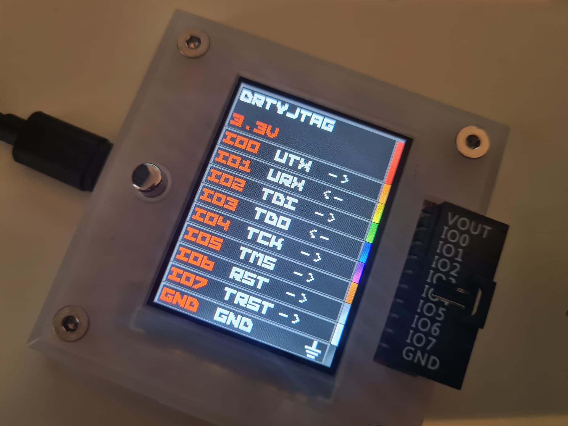
As a minor cosmetic suggestion I would note Vout when normal boot and voltage 3V3 next to it and respectively Vref with measured voltage on pin when booted with button pressed. There is enough space on the screen for that.
My only concern about measuring at startup is that the user might connect the voltage later and get the impression it isn’t working. I’m really not keen to measure in an interrupt loop because that will start impacting the ported code in ways that I may not fully understand.
I loaded this up and gave it a try. Seems to work the same as the previous for me, but now I understand the “hold the button on power up” thing, which I need to do for the 5V target.
Looks just like the first image (VREF <-). Is it supposed to show the 5V coming in the Vout line as discussed above?
I want to hold off on this. Right now my goal is to develop the pirate-lib and a system to build and package all this. Then maybe come back and add some more general features. I’m not keen to do anything that interferes with the ported firmware for fear of introducing bugs in code I don’t fully understand.
Currently the pirate-lib does it’s thing to setup all the hardware, then passes off full control to the ported firmware.
If someone else wants to take a stab at it, please feel free, I’ll accept a pull request. It would involve setting the analog mux to the VOUT pin (ideally in a port of amux.c, as BP5 and BP6 do this differently), then sampling on a timer. Probably need to hack a new function into display.c to position and write just the voltage in that column.
I would take a look, but I have to finally get back to what I’m supposed to be doing, haha. To be honest, I don’t have a current use case for dirtyjtag, but I’m more than willing to test stuff, especially since I had a known working target laying around.